Use method for welding clamp for gas-liquid separator

A gas-liquid separator and welding fixture technology, applied in the field of tooling fixtures, can solve the problems of weak air tightness, poor, and hindering the wide production and use of gas-liquid separators.

Active Publication Date: 2016-03-23
ANHUI ZHONGHUI REFRIGERATION
View PDF6 Cites 4 Cited by
  • Summary
  • Abstract
  • Description
  • Claims
  • Application Information

AI Technical Summary

Problems solved by technology

[0007] In the welding and installation process of the existing gas-liquid separator, the air inlet pipe, air return pipe (outlet pipe) and upper head (upper end cover) are not fixed before welding and are often deflected, unstable or airtight after welding The phenomenon of poor performance can not get the desired installation product in the design, causing serious waste of manpower and material resources, and hindering the widespread production and use of gas-liquid separators. The invention provides a method for using a welding fixture for gas-liquid separators , can effectively fix the relative position of the air inlet pipe, air return pipe (outlet pipe) and upper head (upper end cover), making the welding process more stable and reliable, the workpiece after welding has high precision, high internal cleanliness, and good air tightness. And effectively reduce the input of manpower and material resources, save costs and improve productivity

Method used


Image

  • Use method for welding clamp for gas-liquid separator
  • Use method for welding clamp for gas-liquid separator
  • Use method for welding clamp for gas-liquid separator

Examples


Embodiment 1

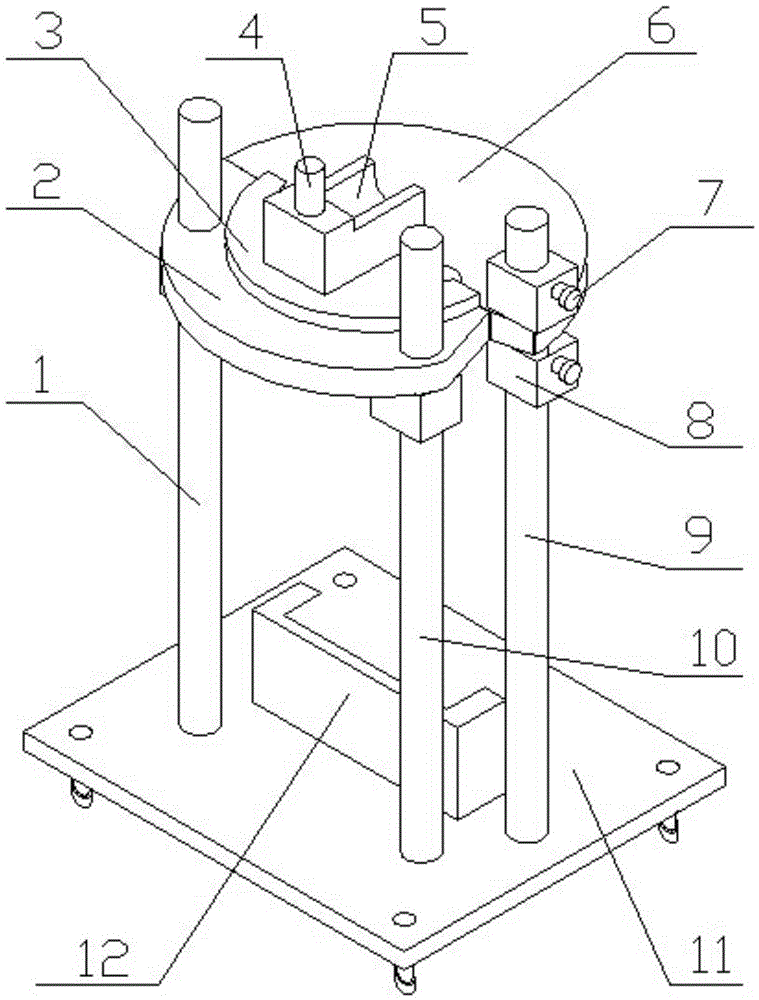
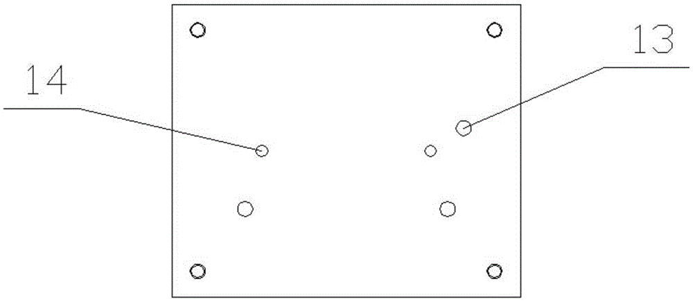
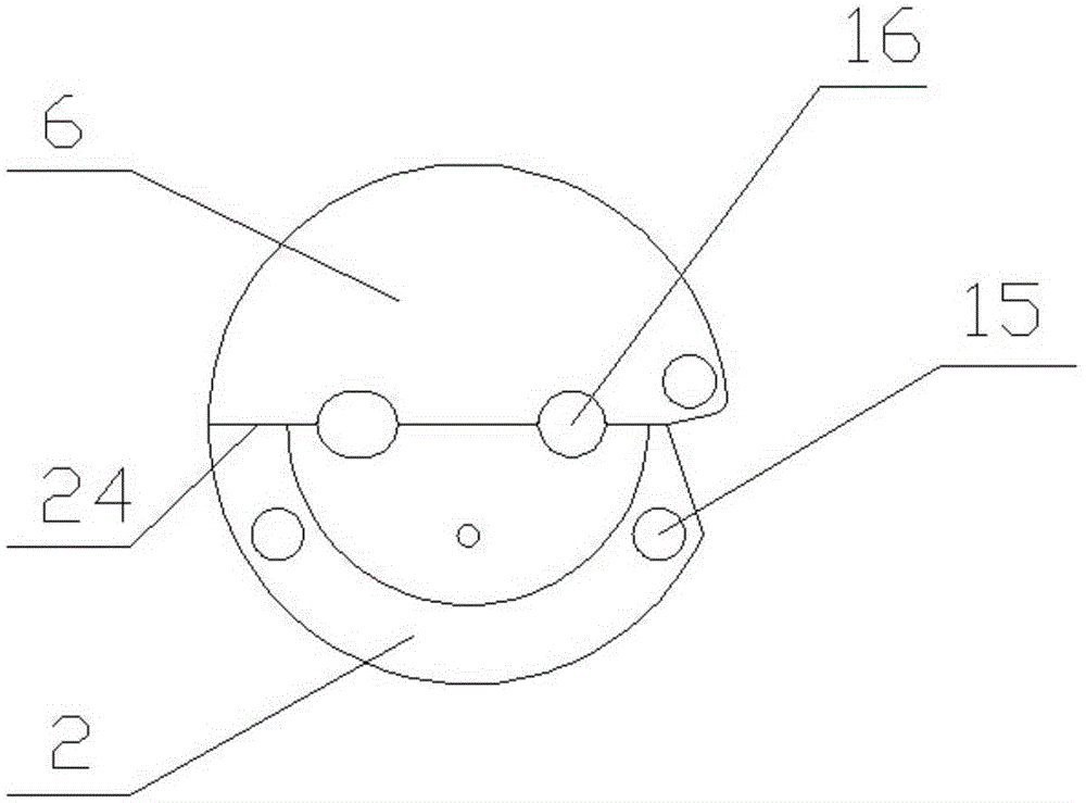
[0053] Such as figure 1 , figure 2 , image 3 , Figure 4 , Figure 5 , Figure 6 , Figure 7 , Figure 8 , Figure 9 , Figure 10 , Figure 11 , Figure 12 and Figure 13 As shown, a gas-liquid separator welding fixture, which includes a first guide post 1, a semi-circular support block 2, a guide post 4, an intake pipe support block 5, a rotating semi-circular support block 6, a positioning block 8, and a second guide post 9 , the third guide post 10, the base 11 and the limit backing plate 12; the base 11 is provided with two limit backing plate mounting holes 14 and three guide post mounting holes 13; the axes of the three guide post mounting holes 13 and the base The connection line of the three intersection points on the upper surface of 11 forms a right triangle; the axis of the two limit back plate installation holes 14 and the connection line of the two intersection points on the upper surface of the base 11 are parallel to the connection line of the three...


PUM


Abstract

The invention discloses a use method for a welding clamp for a gas-liquid separator and belongs to the field of work clamps. The welding clamp comprises a first guide post, a semicircular supporting block, a guide column, a gas inflow pipe supporting block, a rotary semicircular supporting block, a second guide post, a third guide post, a base and a limiting backup plate. The limiting backup plate is fixed to the base. One end of the first guide post and one end of the third guide post are vertically fixed to the base, and the other end of the first guide post and the other end of the third guide post are connected with the semicircular supporting block. One end of the second guide post is vertically fixed to the base, and the other end of the second guide post is connected with the rotary semicircular supporting block. The semicircular supporting block and the rotary semicircular supporting block are each provided with two semicircular grooves. The semicircular grooves of the semicircular supporting block and the semicircular grooves of the rotary semicircular supporting blocks are combined in pairs to form two gas outflow pipe fixing holes. The problems that when the gas-liquid separator is welded, instability is caused, the yield and accuracy are low, and internal oxidation is caused by poor gas shielding during welding can be effectively solved, and the welded workpiece is stable, reliable, high in accuracy and internal cleanliness and good in gas tightness.

Description

[0001] This application is a divisional application of an invention application titled "A Gas-Liquid Separator Welding Fixture and Its Using Method and Manufacturing Method", the application number is 2015100448224, and the application date is January 28, 2015. technical field [0002] The invention belongs to the field of fixtures, and in particular relates to a method for using a welding fixture for a gas-liquid separator. Background technique [0003] The gas-liquid separator is a device that separates the small liquid droplets condensed in the saturated gas to achieve the purpose of condensate recovery or gas phase purification. The gas-liquid separator installed between the suction end of the compressor and the evaporator of the air-conditioning refrigeration system can be used to temporarily store the return liquid of the system, control the return of liquid refrigerant and lubricating oil to the compressor at a safe speed, and avoid hydraulic shock , It can also play ...

Claims


Application Information

Patent Timeline
Patent Type & Authority Applications(China)
IPC IPC(8): B23K37/04
CPCB23K37/04B23K37/0443B23P15/00
Inventor 潘新阳李洪洋
Owner ANHUI ZHONGHUI REFRIGERATION
Why Eureka
Try Eureka