Vehicle-mounted unmanned aerial vehicle net bumping recovery device

A vehicle-mounted drone and recovery device technology, applied in the field of vehicle-mounted drone collision recovery devices, can solve the problems of heavy landing gear structure, reducing the payload of the drone, and large impact load of the drone.

Inactive Publication Date: 2016-03-23
NAT UNIV OF DEFENSE TECH
View PDF5 Cites 8 Cited by
  • Summary
  • Abstract
  • Description
  • Claims
  • Application Information

AI Technical Summary

Problems solved by technology

[0002] The landing method of the existing UAV system generally adopts sliding landing or belly wipe landing, and the landing of the UAV requires the UAV to be equipped with a landing gear. The weight of the landing gear structure greatly reduces the effective use of the UAV. Load capacity; and the taxiing landing requires a long and flat runway, which is greatly restricted in the use of complex terrain mountains or ships
The UAV is subjected to a large impact load when it touches the ground with the belly wipe landing method, especially when the landing attitude deviates or the ground is hard, it is likely to cause damage to the UAV body structure, which greatly shortens the UAV. service life

Method used


Image

  • Vehicle-mounted unmanned aerial vehicle net bumping recovery device
  • Vehicle-mounted unmanned aerial vehicle net bumping recovery device
  • Vehicle-mounted unmanned aerial vehicle net bumping recovery device

Examples


Embodiment Construction

[0024] specific implementation plan

[0025] The present invention will be further described below in conjunction with the accompanying drawings.

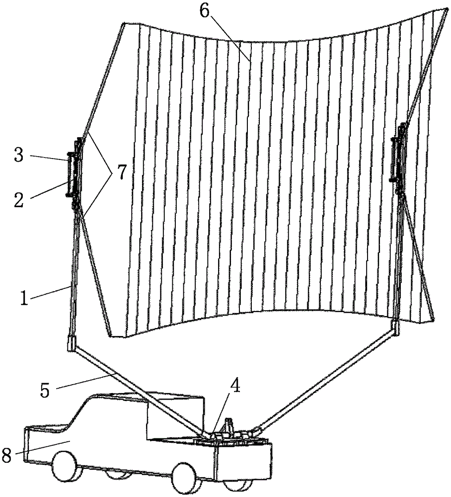
[0026] A vehicle-mounted unmanned aerial vehicle collision net recovery device, such as figure 1 As shown, it includes 2 upright columns 1, 2 link-type synchronization mechanisms 2, 2 damping mechanisms 3, erecting devices 4, 2 support arms 5, recovery net 6, 4 swing bars 7 and vehicle platform 8;

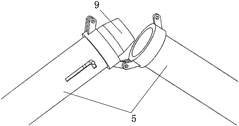
[0027] Such as image 3 As shown, the support arm 5 is assembled from two half-arms, and after the inner pin 9 of one half-arm is inserted into the inside of the other half-arm, the two half-arms are locked by bolts.

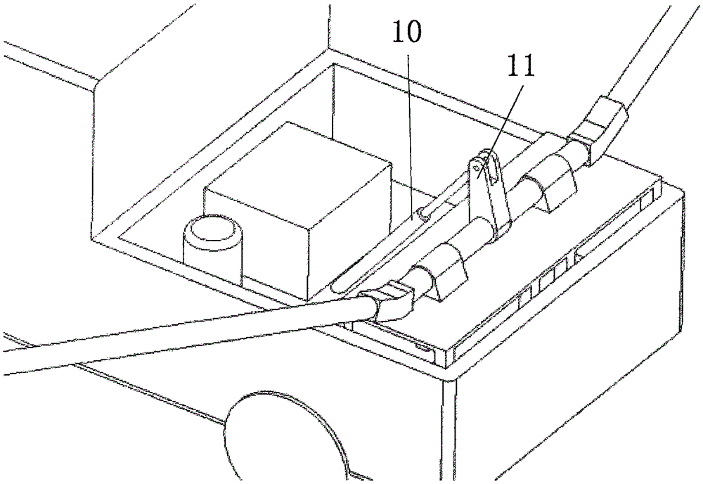
[0028] The erecting device 4 that is fixed on the vehicle platform 8 is as figure 2 As shown, it is composed of a hydraulic system 10 and a lifting arm 11. The hydraulic system 10 is connected to and drives the lifting arm 11. Two support arms 5 are symmetrically and obliquely fixed at both ends of the lifting arm 11,...


PUM


Abstract

The invention belongs to the technical field of unmanned aerial vehicles, and relates to a vehicle-mounted unmanned aerial vehicle net bumping recovery device which comprises stand columns, connecting rod type synchronization mechanisms, damping mechanisms, supporting arms, a recovery net, oscillating bars and a vehicle platform. The two supporting arms are symmetrically and obliquely fixed to the vehicle platform; the stand columns are vertically downwards fixed to the top ends of the supporting arms in the vertical direction. One connecting rod type synchronization mechanism is fixed to the top end of each stand column; each connecting rod type synchronization mechanism is composed of a mechanism main rod, a first oscillating arm and a second oscillating arm, wherein the first oscillating arm and the second oscillating arm are fixed to the two ends of the mechanism main rod through rotating shafts, and the first oscillating arm and the second oscillating arm are connected together through a connecting rod. The top end of each first oscillating arm and the top end of each second oscillating arm are each connected with one oscillating bar, and the recovery net is fixed to the ends of the four oscillating bars. A nose of an unmanned aerial vehicle rushes at the net face of the recovery net 6 in the direction from a vehicle head to a vehicle tail. Wings of the unmanned aerial vehicle generate pull force to the recovery net 6 and drive the oscillating bars 7 to move to transmit the force to the stand columns 1; at last, the damping mechanisms 3 connected with the stand columns 1 complete energy absorption, and the unmanned aerial vehicle is safely recovered.

Description

technical field [0001] The invention belongs to the technical field of unmanned aerial vehicles, and relates to a vehicle-mounted unmanned aerial vehicle collision net recovery device. Background technique [0002] The landing method of the existing UAV system generally adopts sliding landing or belly wipe landing, and the landing of the UAV requires the UAV to be equipped with a landing gear. The weight of the landing gear structure greatly reduces the effective use of the UAV. Load capacity; and the taxiing landing requires a long and flat runway, and its use in complex terrain mountains or ships is greatly restricted. The UAV is subjected to a large impact load when it touches the ground with the belly wipe landing method, especially when the landing attitude deviates or the ground is hard, it is likely to cause damage to the UAV body structure, which greatly shortens the UAV. service life. Contents of the invention [0003] The technical problem to be solved by the p...

Claims


Application Information

Patent Timeline
Patent Type & Authority Applications(China)
IPC IPC(8): B64F1/02
CPCB64F1/02B64U70/30
Inventor 侯中喜郭正王胤骎杨希祥刘珏闫秋飞陈清阳鲁亚飞蒋洁
Owner NAT UNIV OF DEFENSE TECH
Why Eureka
Try Eureka