Blade adjusting structure

A technology for adjusting blades and adjusting parts, which is applied in the field of compressors

Inactive Publication Date: 2016-03-23
AECC SHENYANG ENGINE RES INST
View PDF4 Cites 5 Cited by
  • Summary
  • Abstract
  • Description
  • Claims
  • Application Information

AI Technical Summary

Problems solved by technology

[0005] The object of the present invention is to provide a blade adjustment structure to solve or at least alleviate at least one of the problems existing in the technical background

Method used


Image

  • Blade adjusting structure
  • Blade adjusting structure

Examples


Embodiment Construction

[0026] In order to make the objectives, technical solutions and advantages of the present invention clearer, the technical solutions in the embodiments of the present invention will be described in more detail below in conjunction with the drawings in the embodiments of the present invention. In the drawings, the same or similar reference numerals denote the same or similar elements or elements having the same or similar functions throughout. The described embodiments are some, but not all, embodiments of the invention. The embodiments described below by referring to the figures are exemplary and are intended to explain the present invention and should not be construed as limiting the present invention. Based on the embodiments of the present invention, all other embodiments obtained by persons of ordinary skill in the art without creative efforts fall within the protection scope of the present invention. Embodiments of the present invention will be described in detail below ...


PUM


Abstract

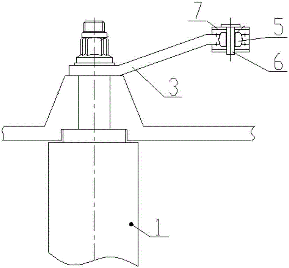
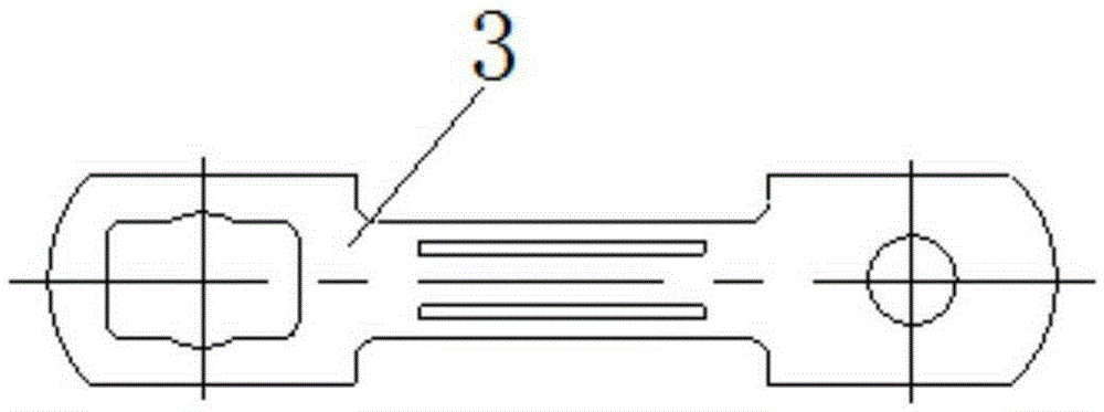
The invention discloses a blade adjusting structure and relates to the technical field of gas compressor. The blade adjusting structure comprises a rocker arm (3), a linkage ring (7), a positioning pin (6) and a rotating adjusting piece (5), wherein one end of the rocker arm (3) is connected with a static sub-blade (1), and the other end of the rocker arm (3) is provided with a mounting hole for the rotating adjusting piece (5); a through hole is formed in the center of the rotating adjusting piece (5), the positioning pin (6) passes through the through hole to connect the linkage ring (7) with the rotating adjusting piece (5); and the rotating adjusting piece (5) can rotate around the positioning pin (6). The blade adjusting structure has the benefits that the rotating adjusting piece is arranged at one end, connected with the linkage ring, of the rocker arm, and the rotating adjusting piece is connected with the linkage ring and the rocker arm by the positioning pin and can rotate around the positioning pin, thus avoiding the phenomenon that the blade adjusting precision is affected due to deformation of the rocker arm when the linkage ring rotates around self rotating shaft.

Description

technical field [0001] The invention relates to the technical field of compressors, in particular to a blade adjustment structure. Background technique [0002] Compressor surge is a problem that multi-stage axial flow compressors always have to face, that is, when the engine is working in a non-design state, the flow capacity of the supercharging stage in front of the compressor and the supercharging stage behind the compressor do not match, resulting in front surge and rear vortex or Vortex and pant. In order to ensure the stable operation of the compressor, it is necessary to reasonably control the air flow through the various stages of the compressor, usually using the adjustment method of the compressor's rotatable guide vane. [0003] The adjustment mechanism of the rotatable guide vane: through the actuator, the linkage ring is driven to rotate around its own rotation axis, and the rocker arm is driven to rotate around the upper journal of the stator blade, thereby d...

Claims


Application Information

Patent Timeline
Patent Type & Authority Applications(China)
IPC IPC(8): F04D29/56F04D27/02
CPCF04D29/563F04D27/0246
Inventor 李孝堂印雪梅张岩韩方军王华刘冬袁森张鑫杨勇刚
Owner AECC SHENYANG ENGINE RES INST
Why Eureka
Try Eureka