Linear-motion bearing with flange attached

A technology of linear motion bearings and flanges, applied in the direction of linear motion bearings, bearings, shafts and bearings, etc., can solve the problems of high cost, achieve high adhesion, high joint strength, and improve the effect of joint strength

Active Publication Date: 2016-03-23
HIHAISUTO SEIKO
View PDF8 Cites 2 Cited by
  • Summary
  • Abstract
  • Description
  • Claims
  • Application Information

AI Technical Summary

Problems solved by technology

However, the method of integrally molding the flanged outer cylinder with a metal material is expensive, so it cannot be said to be advantageous as an industrial method.
In particular, there is a problem that, in the case of manufacturing a large number of flanged outer cylinders having the same shape but with different flange shapes or attachment positions, it is necessary to have a mold corresponding to each flange shape or attachment position.
However, in order to securely fix the flange to the outer cylinder, it is necessary to form claws and claw insertion holes on the flange and the outer cylinder in advance, so this cannot be said to be an advantageous method as an industrial method for the flanged outer cylinder.

Method used


Image

  • Linear-motion bearing with flange attached
  • Linear-motion bearing with flange attached
  • Linear-motion bearing with flange attached

Examples


Embodiment Construction

[0019] First, a representative embodiment of the flanged linear motion bearing of the present invention will be described with reference to the drawings.

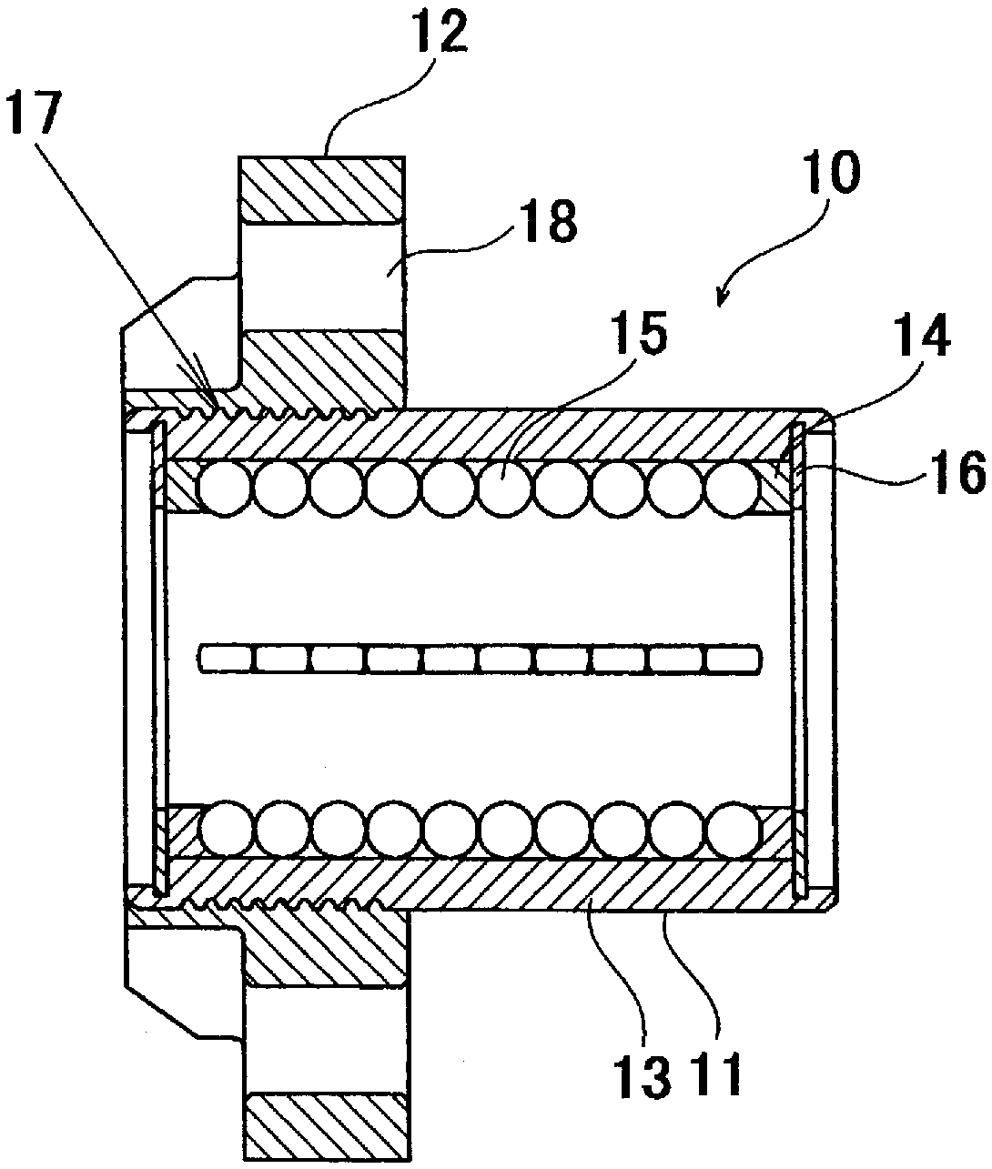
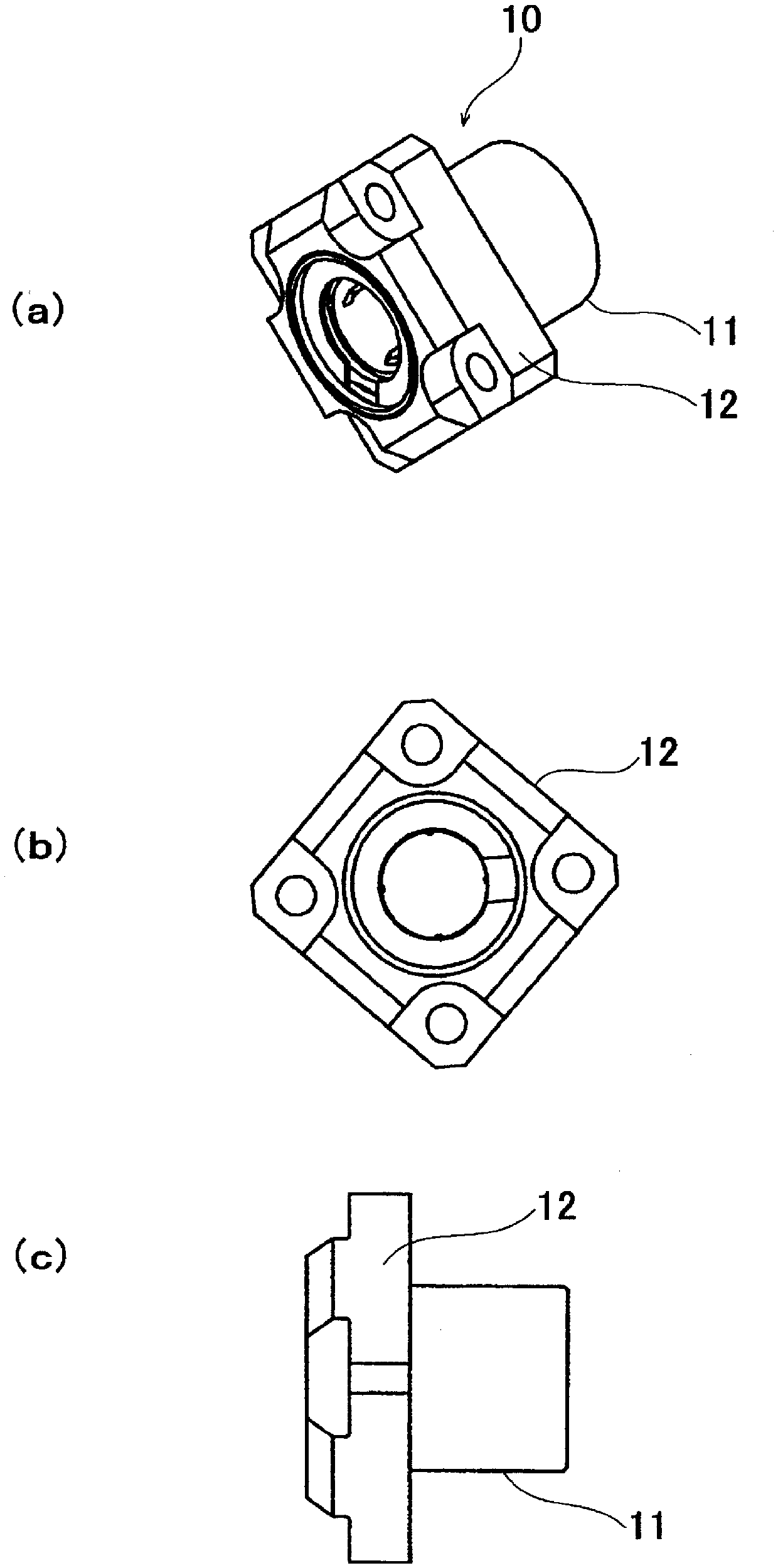
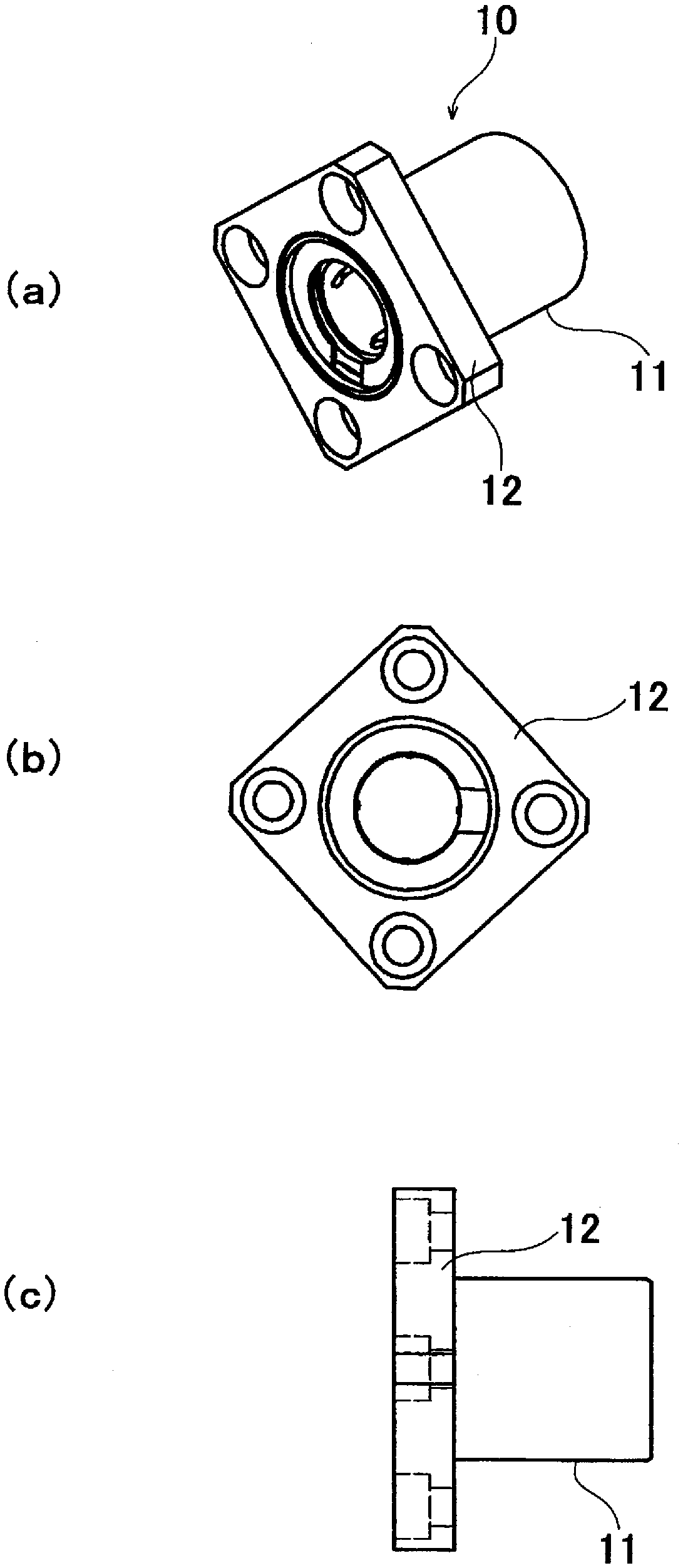
[0020] in figure 1 Here, a perspective view (a), a bottom view (b), and a side view (c) of a configuration example of the flanged linear motion bearing 10 of the present invention are shown. in figure 1 In the shown flanged linear motion bearing 10, a ribbed flange 12 is formed on one end of the linear motion bearing 11. The linear motion bearing 11 may use a linear motion bearing having a general structure of a linear motion bearing, that is, it includes an outer cylinder, a cylindrical rolling element cage fitted inside the outer cylinder, and a cylindrical rolling element cage held in the cylindrical rolling element cage. Multiple rolling elements. As the linear motion bearing, an infinite loop type linear motion bearing and a non-infinite loop type linear motion bearing are known, and either of them can be used. In add...


PUM


Abstract

[Problem] To provide an easily manufactured linear-motion bearing with a flange attached. [Solution] A linear-motion bearing with a flange attached in which: the linear-motion bearing includes an outer tube that comprises a metal material, a tubular rolling-element holder that is fitted inside the outer tube, and a plurality of rolling elements that are held by the tubular rolling-element holder; and the flange is annularly provided to the circumference of the outer tube of the linear-motion bearing. The linear-motion bearing with a flange attached is characterized in that the flange is formed by a mold being arranged on the circumference of the outer tube of the linear-motion bearing, a fluid resin material being poured into the mold, and the material being hardened.

Description

Technical field [0001] The present invention relates to a flanged linear motion bearing in which an annular flange is arranged around an outer cylinder of a linear motion bearing. Background technique [0002] The linear motion bearing (linear bearing) supports the shaft body inserted into the bearing and makes the shaft body slide smoothly in the linear direction (ie, the axial direction) caused by the driving force applied along the axial direction of the shaft body The possible mechanical parts are assembled into various mechanical devices for use. [0003] Linear motion bearings usually consist of an outer cylinder made of a metal material, a cylindrical rolling element cage (ball bearing cage) fitted inside the outer cylinder, and a plurality of rolling elements held by the cylindrical rolling element cage (Ball bearing) composition. The shaft is inserted into the inner side of the cylindrical rolling element holder, and is supported by a plurality of rolling elements partia...

Claims


Application Information

Patent Timeline
Patent Type & Authority Applications(China)
IPC IPC(8): F16C29/04
CPCF16C29/0602F16C29/0676
Inventor 桥口一平进藤繁树福留弘人
Owner HIHAISUTO SEIKO
Why Eureka
Try Eureka