
an unpacking device

A packaging box and driver technology, applied in the field of packaging machinery, can solve the problems of high production cost, low efficiency, and high management cost, and achieve the effects of low management cost, low control cost, and accurate and stable motion stroke

Active Publication Date: 2018-09-25
HANGZHOU ZHONGYA MACHINERY CO LTD
View PDF5 Cites 0 Cited by
  • Summary
  • Abstract
  • Description
  • Claims
  • Application Information

AI Technical Summary

Problems solved by technology

[0003] The unpacking operation of the above-mentioned packing box 9 is generally realized manually, that is, the packing box 9 that can hold articles is obtained by applying force by the worker, and the packing box 9 changes from a sheet structure to a three-dimensional box structure, and the manual unpacking operation The disadvantages are low efficiency, high production cost and high management cost

Method used


Image

  • an unpacking device
  • an unpacking device
  • an unpacking device

Examples


Embodiment 1

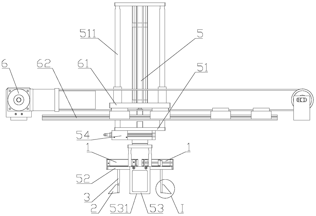
[0043] Such as image 3 , Figure 4 with Figure 5 As shown, the present invention provides a kind of unpacking device, comprises unpacking part, elevating part, shaping part and material moving part, and elevating part drives unpacking part lifting, and material moving part drives elevating part, unpacking part from sheet structure Linear reciprocating motion is performed between the area where the packing box is located and the area where the shaped parts are located.

[0044] The material shifting part drives the lifting part and the unpacking part to move above the storage area of ​​the packing box of the sheet structure, and then the lifting part drives the unpacking part to descend, and the unpacking part performs unpacking operation on the packing box of the sheet structure, and then the lifting part Drive the unpacking part to lift, the packing box on the unpacking part moves with the unpacking part, and then the moving part drives the lifting part, the unpacking par...

Embodiment 2

[0060] The material moving part can be omitted on the basis of the first embodiment. It is necessary to manually install the packing box on the unpacking part, and then the unpacking part is driven by the lifting part during the unpacking operation, and the packing box is sent to the shaping area of ​​the shaping part, and then the unpacking part is separated from the packing case, and the lifting part Drive the unpacked parts out of the shaping area.

Embodiment 3

[0062] If it is only to realize the automatic unpacking operation, it can be realized only by unpacking parts, that is, the unpacking device of this embodiment only includes unpacking parts, and the lifting parts, shaping parts and material moving parts are omitted on the basis of Embodiment 1. Manual loading of the box on the unboxed parts is required. After the packaging box is unpacked by the unpacking part, it can maintain the box structure in an ideal unfolded state, so the automatic unpacking can be realized without the cooperation of the shaped parts. After the packing box is through the unpacking operation of the unpacking part, it falls off from the unpacking part and is manually taken away, or the packing case can also be taken away by other devices.


PUM


Abstract

The invention discloses a box unpacking device, belonging to the field of packing machinery, and the problems in the prior art that manual box unpacking is low in efficiency and high in cost are solved. The technical scheme for solving the problem is characterized in that the box unpacking device comprises a box unpacking component, wherein the box unpacking component comprises box unpacking drivers and box unpacking operation parts; the box unpacking drivers are provided with output ends; the box unpacking operation parts are arranged on the output ends of the box unpacking drivers; the box unpacking drivers drive the box unpacking operation parts to linearly reciprocate; at least two box unpacking operation parts are arranged; the moving directions of the box unpacking operation parts are parallel driven by the box unpacking drivers, wherein the moving direction of at least one box unpacking operation part driven by the corresponding box unpacking driver is opposite to the moving direction of the other box unpacking operation part driven by the corresponding box unpacking driver; each box unpacking operation part is provided with a guiding surface and an insertion end; the facing direction of each guiding surface is oblique toward the moving direction of the corresponding box unpacking operation part driven by the corresponding box unpacking driver; and each insertion end is located on one end of the corresponding guiding surface. The box unpacking device is mainly applied to box unpacking operation of a packing box.

Description

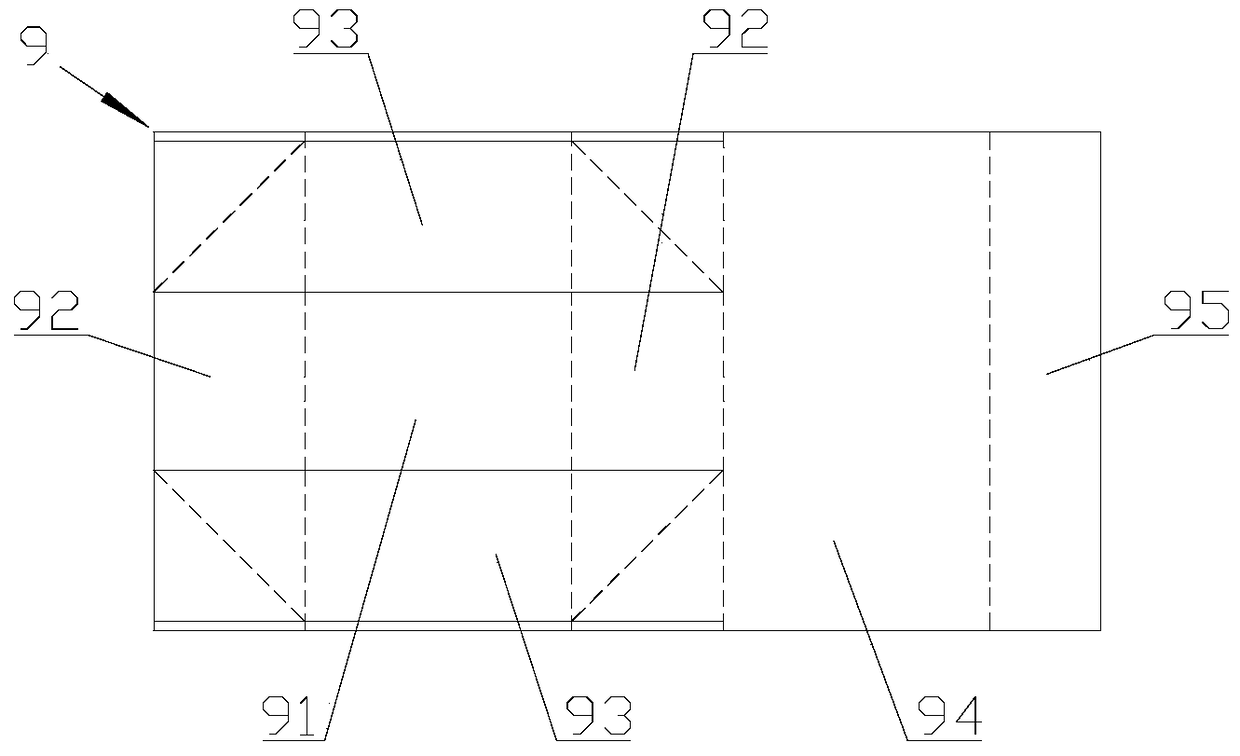
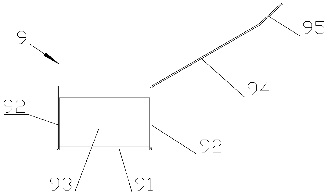
technical field [0001] The invention relates to a packaging machine, in particular to an unpacking device. Background technique [0002] With the development of packing box technology, there are more and more forms of packing boxes, especially the packing boxes that can be put into packing operation only by unfolding, such as figure 1 The shown packing box 9 generally comprises a base plate 91, two length side plates 92, two width side plates 93, a top plate 94 and a connecting plate 95, and the two ends of a width side plate 93 are respectively connected to the two length sides. One end of the board 92 is connected, and the two ends of the other width side board 93 are respectively connected with the other ends of the two length side boards 92, and crease lines are set at both ends of the width side board 93, specifically the ends of the width side board 93 Covering the end of the length side plate 92, the end of the width side plate 93 is provided with a crease line incli...

Claims


Application Information

Patent Timeline
Patent Type & Authority Patents(China)
IPC IPC(8): B65B69/00
CPCB65B69/00
Inventor 史中伟史正姜钰
Owner HANGZHOU ZHONGYA MACHINERY CO LTD
Learn More