

Box unpacking device
A press box and driver technology, applied in the field of packaging machinery, can solve the problems of high production cost, low efficiency, and high management cost, and achieve the effects of low management cost, low control cost, and accurate and stable motion stroke
- Summary
- Abstract
- Description
- Claims
- Application Information
AI Technical Summary
Problems solved by technology
Method used
Image

Examples
Embodiment 1
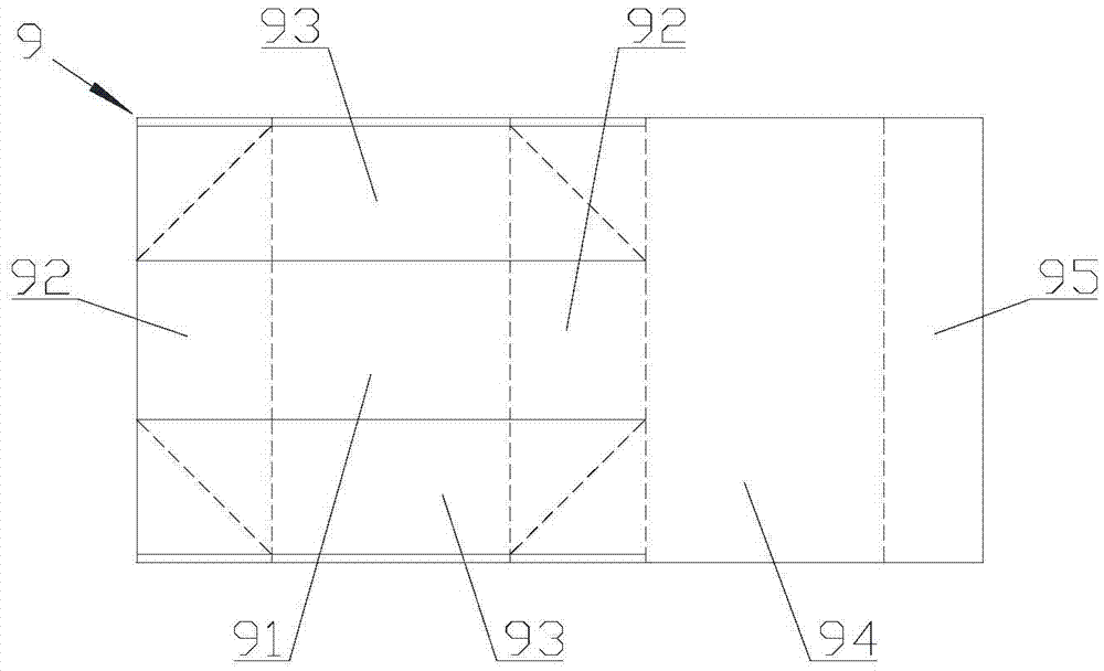
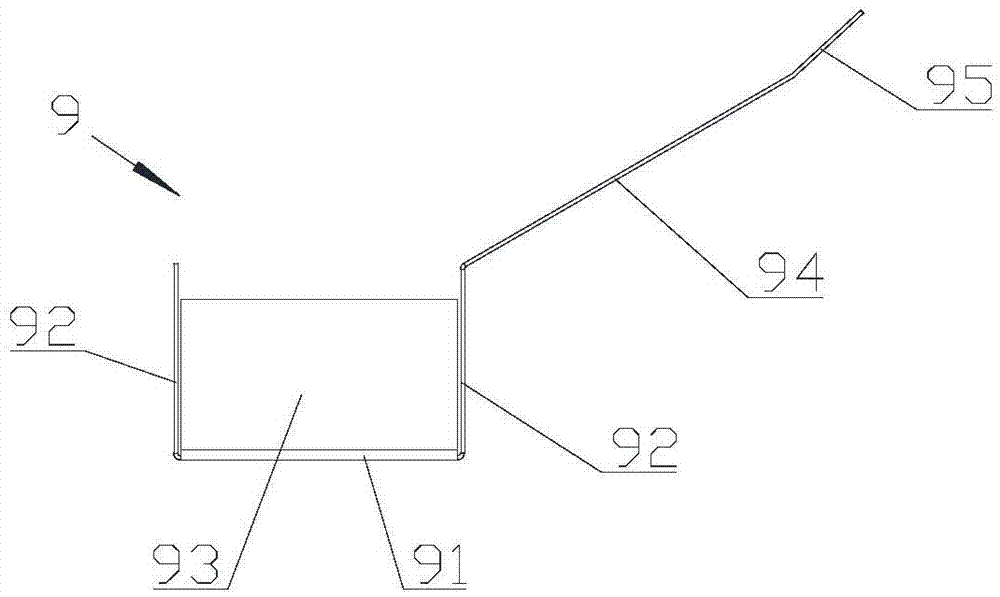
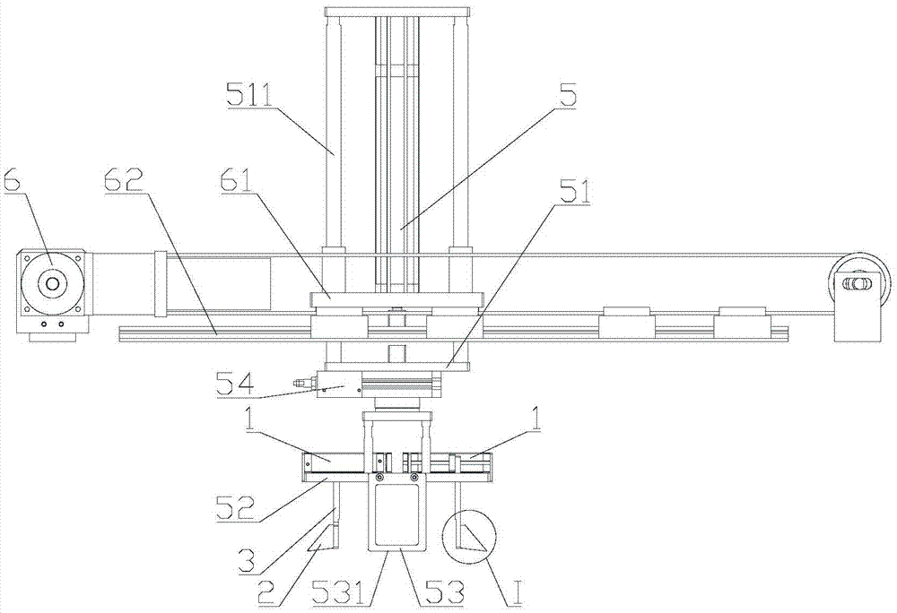
[0043] Such as image 3 , Figure 4 and Figure 5 As shown, the present invention provides a kind of unpacking device, comprises unpacking part, elevating part, shaping part and material moving part, and elevating part drives unpacking part lifting, and material moving part drives elevating part, unpacking part from sheet structure Linear reciprocating motion is performed between the area where the packing box is located and the area where the shaped parts are located.
[0044] The material shifting part drives the lifting part and the unpacking part to move above the storage area of the packing box of the sheet structure, and then the lifting part drives the unpacking part to descend, and the unpacking part performs unpacking operation on the packing box of the sheet structure, and then the lifting part Drive the unpacking part to lift, the packing box on the unpacking part moves with the unpacking part, and then the moving part drives the lifting part, the unpacking part...
Embodiment 2
[0060] The material moving part can be omitted on the basis of the first embodiment. It is necessary to manually install the packing box on the unpacking part, and then the unpacking part is driven by the lifting part during the unpacking operation, and the packing box is sent to the shaping area of the shaping part, and then the unpacking part is separated from the packing case, and the lifting part Drive the unpacked parts out of the shaping area.
Embodiment 3
[0062] If it is only to realize the automatic unpacking operation, it can be realized only by unpacking parts, that is, the unpacking device of this embodiment only includes unpacking parts, and the lifting parts, shaping parts and material moving parts are omitted on the basis of Embodiment 1. Manual loading of the box on the unboxed parts is required. After the packaging box is unpacked by the unpacking part, it can maintain the box structure in an ideal unfolded state, so the automatic unpacking can be realized without the cooperation of the shaped parts. After the packing box is through the unpacking operation of the unpacking part, it falls off from the unpacking part and is manually taken away, or the packing case can also be taken away by other devices.
PUM
 Abstract
Description
Claims
Application Information