A lobby background wall and its manufacturing process

A production process and background wall technology, applied in covering/lining, building, building structure, etc., can solve the problems of human harm, high construction cost, inconvenient construction, etc., achieve good sound insulation and noise reduction effect, simple structure and process , increase the effect of beauty

Active Publication Date: 2018-10-26
福建森源木作有限公司
View PDF8 Cites 0 Cited by
  • Summary
  • Abstract
  • Description
  • Claims
  • Application Information

AI Technical Summary

Problems solved by technology

[0003] At present, the lobby background walls of hotels, hotels, movie theaters and other buildings are relatively large in size, so stone is generally used to make the background wall. However, there are several problems with stone as the material of the background wall. First, the construction is inconvenient, and stones of different sizes It is necessary to select and process materials according to the specific conditions of the site, and then splicing the heavy stones to the wall to form a complete wall. The construction cost is relatively high; second, most of the stones are radioactive, and most of them are harmful to the human body. ; The third is to install a stone background wall in the lobby, which may give people a cold and heavy feeling
[0004] In order to overcome the above problems, the lobby of some high-end buildings uses panels to make background walls, but the existing panel background walls are generally engraved to increase the aesthetic feeling, the process is relatively complicated, and it is easy to give people a heavy feeling. The plank background wall will also make the visual space of the lobby smaller than the actual space, affecting the beauty of the lobby

Method used


Image

  • A lobby background wall and its manufacturing process
  • A lobby background wall and its manufacturing process
  • A lobby background wall and its manufacturing process

Examples


Embodiment Construction

[0038] The present invention will be further described below in conjunction with the accompanying drawings and specific embodiments.

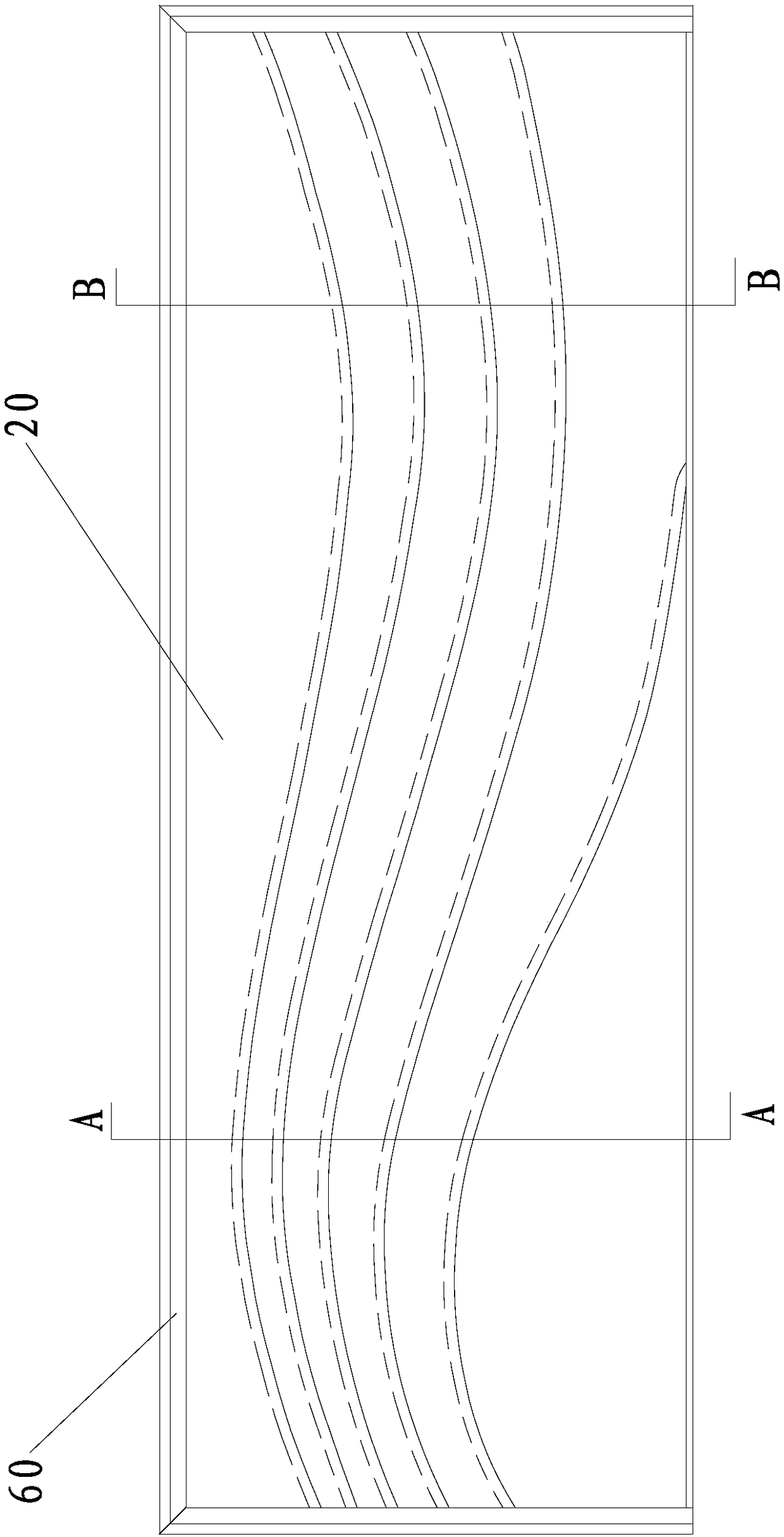
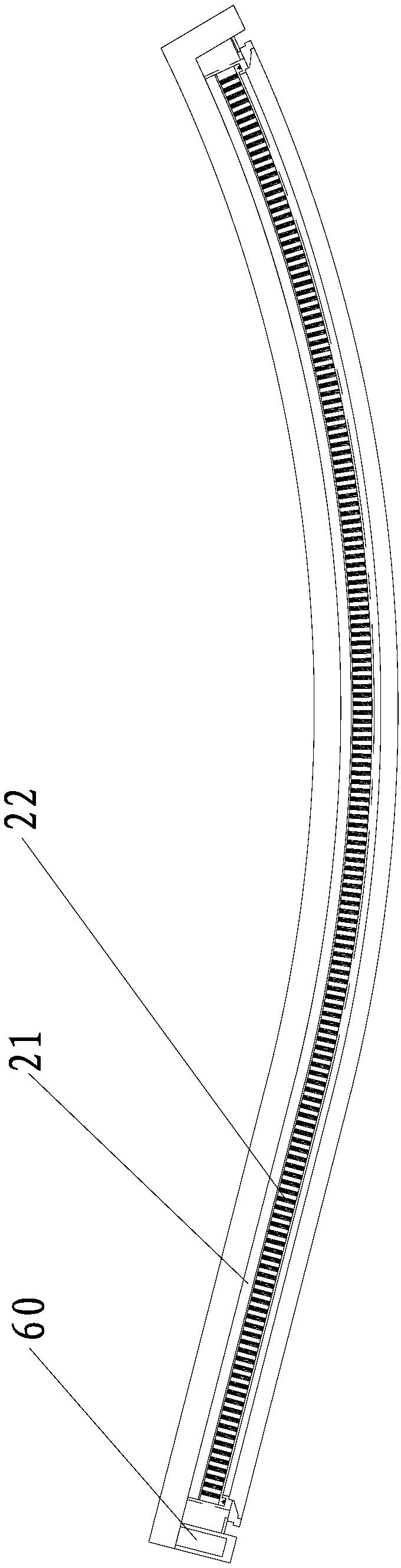
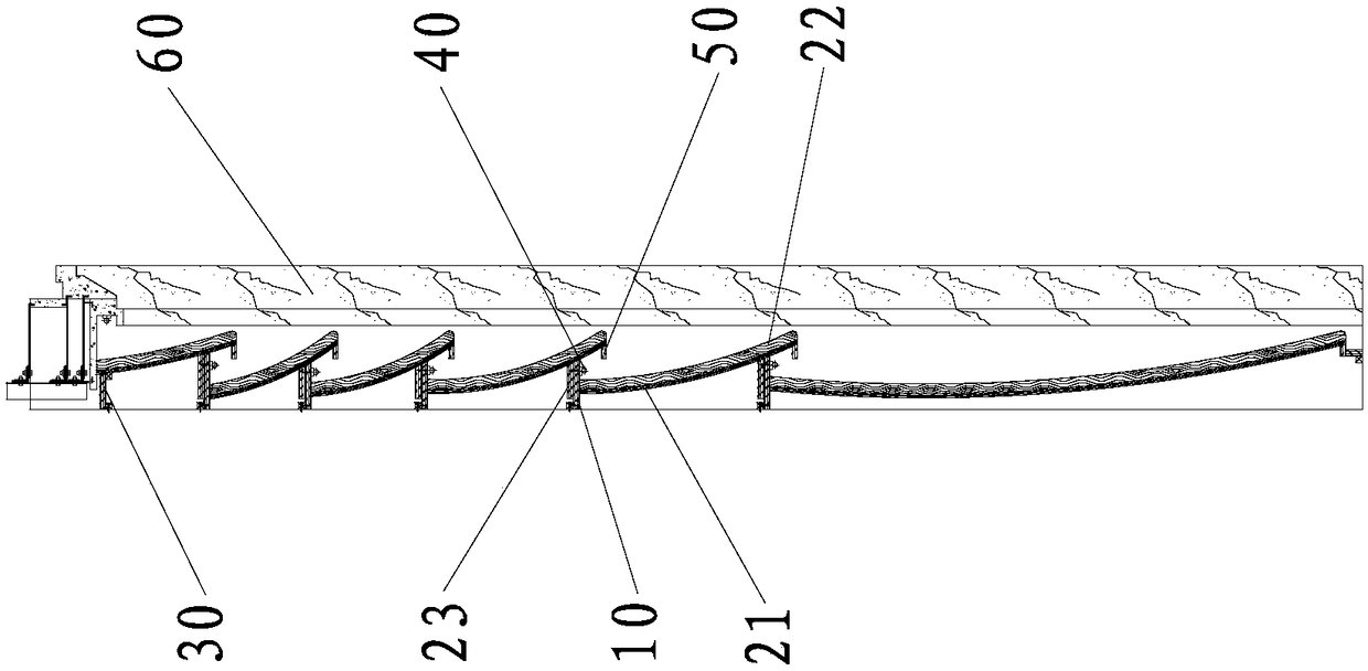
[0039] like Figure 1-5 As shown, the lobby background wall provided by this embodiment includes a plurality of wavy base panels 10 and a plurality of wave units 20 stacked in sequence from the floor to the ceiling, and of course may also include a wall frame for defining the boundary of the wall 60. The wall frame 60 can be a conventional background wall frame, which is not the focus of the present invention, and will not be described in detail here.

[0040] Each base plate 10 is located at the position where every two adjacent wave units 20 overlap each other, that is, the number of base plates 10 is one less than the number of wave units 20. In this embodiment, there are six wave units 20 , the six wave units 20 are stacked together sequentially. For the convenience of expression, in this embodiment, each wave unit 20 is referred to as the...


PUM


Abstract

The invention provides a hall background wall which comprises basic layer plates and a plurality of wave units stacked in sequence. Each basic layer plate is located at the stacking position of every two corresponding adjacent wave units. The horizontal section of each wave unit is in an arc shape, and the end faces of the stacking position of every two adjacent wave units are wave faces. Each wave unit comprises an arc-shaped plate and a plurality of battens which are fixed to the front face of the arc-shaped plate at equal intervals and located in the vertical plane. The upper ends of the arc-shaped plates are fixed to a ceiling or the plate bodies of the basic layer plates, and the lower ends of the arc-shaped plates are fixed to a floor or suspended. The plate bodies of the arc-shaped plates with the suspended lower ends abut against the ends, away from the wall, of the basic layer plates. The invention further provides a manufacturing process of the hall background wall. The wave units are arranged, so that the whole hall background wall is well proportioned in a concave-convex mode, a stereoscopic wave shape is formed, and the visual space is relatively large. Due to the fact that no pattern needs to be carved, the structure and the process are simple.

Description

technical field [0001] The invention relates to a decorative wall and its manufacturing process, in particular to a lobby background wall and its manufacturing process. Background technique [0002] The background wall is a kind of decoration on the wall. It can not only be applied to the home decoration decoration of the TV background wall, sofa background wall, porch background wall and bedroom lamp in the family living room, but also can be used in hotels, hotels, performing arts halls, cinemas, recording Room and other wall decoration. [0003] At present, the lobby background walls of hotels, hotels, movie theaters and other buildings are relatively large in size, so stone is generally used to make the background wall. However, there are several problems with stone as the material of the background wall. First, the construction is inconvenient, and stones of different sizes It is necessary to select and process materials according to the specific conditions of the site...

Claims


Application Information

Patent Timeline
Patent Type & Authority Patents(China)
IPC IPC(8): E04F13/08E04F13/076
CPCE04F13/0871E04F13/0889
Inventor 陈远文黄文清
Owner 福建森源木作有限公司
Why Eureka
Try Eureka