
Foot control turning mechanism

A technology of flipping mechanism and foot control, applied in the direction of conveyor, conveyor objects, transportation and packaging, etc., can solve the problem of inapplicable fine operation, etc., and achieve the effect of convenient force adjustment.

Inactive Publication Date: 2017-07-14
重庆科谷机械有限公司
View PDF1 Cites 0 Cited by
  • Summary
  • Abstract
  • Description
  • Claims
  • Application Information

AI Technical Summary

Problems solved by technology

[0004] Turning over by a motor is not suitable for fine operations in general handicrafts, such as processing buttons, which require manual operations by handicraftsmen to achieve fine processing

Method used


Image

  • Foot control turning mechanism
  • Foot control turning mechanism

Examples


Embodiment Construction

[0019] The present invention will be described in further detail below by means of specific embodiments:

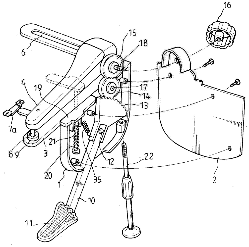
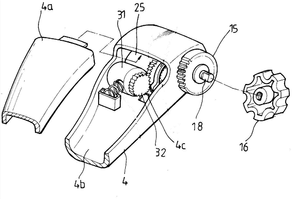
[0020] The reference signs in the drawings of the description include: rotating rod 10, pedal 11, hinge point 12, limit rod 22, teeth 13, rotating shaft 17, second gear 14, rotating gear 15, pin shaft 18, collar 6 , ear plate 7a, upper cover plate 19, connecting column 20, return spring 21, compression spring 35, support frame 1, side plate 2, gear cover 16, upper mold 8, lower mold 9, base plate 3, rotating cover plate 4, The upper plate 4a and the lower groove 4b.

[0021] The embodiment is basically as attached figure 1 As shown: the foot-controlled turning mechanism of this embodiment includes a rotating rod 10, a support frame 1, a bottom plate 3 and a rotating cover plate 4, the bottom plate 3 is fixed on the support frame 1, and the support frame 1 passes through figure 1 The lug 7a shown is secured with the collar 6 to other fixings.

[0022] One end of the rot...


PUM


Abstract

The invention discloses a turnover mechanism, and particularly relates to a foot control turnover mechanism. The foot control turnover mechanism comprises a rotary rod, a supporting frame, a bottom plate and a rotary cover plate. One end of the rotary cover plate is hinged to the bottom plate, and an upper mold is arranged at the other end of the rotary cover plate. A lower mold corresponding to the upper mold in position is arranged on the bottom plate. The rotary rod is hinged to the supporting frame, a pedal is arranged at one end of the rotary rod, and a row of teeth is arranged at the other end of the rotary rod. A rotary gear is arranged on the supporting frame, and a pin shaft is arranged between the rotary gear and the supporting frame. The gear is fixed to the pin shaft, and the pin shaft is rotatably connected to the supporting frame. A second gear for transmission is arranged between the teeth and the rotary gear. A first shaft gear is arranged on the bottom plate, the pin shaft penetrates the supporting frame and is fixedly connected with the first shaft gear, and a limiting mechanism for limiting the rotating angle of the first shaft gear is arranged on the bottom plate. The technical defect that manual operation is inconvenient in the prior art is overcome, and the foot control turnover mechanism is suitable for fine manufacturing of handicraft products.

Description

technical field [0001] The invention relates to a turning mechanism, in particular to a foot-controlled turning mechanism. Background technique [0002] The existing overturning machines usually place the object to be overturned on the overturning surface, and then overturn it. For example, Chinese patent CN102358509 provides a turning mechanism, which includes a frame, a turning platform that is arranged on the frame and can be turned over relative to the frame, and a turning motor that controls the turning platform. The turning platform consists of two The inverting surface arranged in parallel is connected and formed on the inverting frame; it also includes a pressing structure, and the pressing structure includes a set of pressing blocks and a pressing motor for controlling the distance between the pressing blocks; the turning The surface is composed of two groups of conveying structures, each group of conveying structures includes a roller shaft and a conveyor belt arr...

Claims


Application Information

Patent Timeline
Patent Type & Authority Patents(China)
IPC IPC(8): B65G47/248
CPCB65G47/248B65G2201/02
Inventor 龚东亚
Owner 重庆科谷机械有限公司
Learn More