Eureka AIR delivers breakthrough ideas for toughest innovation challenges, trusted by R&D personnel around the world.
Cardiovascular compression device
What is Al technical title?
Al technical title is built by PatSnap Al team. It summarizes the technical point description of the patent document.
A cardiovascular and surface-fixed technology, which is applied in the field of medical devices, can solve the problems of increased work difficulty for medical staff, threats to the safety of patients, and small contact area, so as to improve convenience, expand the scope of use, and ensure physical safety.
Inactive Publication Date: 2018-02-23
杨晓飞
View PDF4 Cites 0 Cited by
Summary
Abstract
Description
Claims
Application Information
AI Technical Summary
This helps you quickly interpret patents by identifying the three key elements:
Problems solved by technology
Method used
Benefits of technology
Problems solved by technology
[0002] At present, after percutaneous puncture of cardiovascular angiography, manual compression is generally used for hemostasis at the puncture site during femoral artery extubation and after extubation. Although the purpose of hemostasis can be achieved, medical staff usually press continuously for more than 30 minutes. The labor intensity is very high, which increases the difficulty of work for medical staff
Even though there are currently some compression hemostasis devices on the market, due to their complex structure, inconvenient operation, and small contact area with the parts that need to be pressed, compression hemostasis operations are performed in time from time to time, threatening the life safety of patients
Method used
Image
Click on the blue label to locate the original text in one second.
Reading with bidirectional positioning of images and text.
Examples
Embodiment Construction
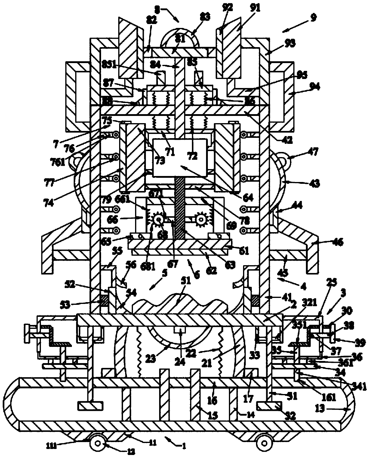
[0008] like figure 1 As shown, the compression device for cardiovascular imaging of the present invention includes a base plate device 1, a support plate 2 located above the base plate device 1, an adjustment device 3 located on the left and right sides of the support plate 2, and a bracket located above the support plate 2. Device 4, a positioning device 5 located inside the bracket device 4, a pressing device 6 located above the positioning device 5, a driving device 7 located above the pressing device 6, a holding device located above the driving device 7 8 and friction devices 9 located on the left and right sides of the gripping device 8 .
[0009] like figure 1 As shown, the base plate device 1 includes a base plate, a first support block 11 located under the base plate, a first roller 12 located under the first support block 11, and first bending rods located on the left and right sides of the base plate. 13. The first support rods 14 located on the left and right sid...
PUM
Abstract
An angiocardiography pressing device comprises a base plate device, a supporting plate, an adjusting device, a support device, a positioning device, a pressing device, a driving device, a holding device and a friction device, wherein the base plate device comprises a base plate, a first supporting block, a first roller, a first bent rod, a first supporting rod, a first positioning rod, a first cross plate and a first positioning block, a second bent rod, a first spring, a first elastic rod, a second positioning block and a first support are arranged on the supporting plate, the adjusting device comprises a first rotary rod, a third positioning block, a first positioning frame, a first gear, a first rotary shaft, a second support, a second gear, a second rotary shaft, a first rotary part and a second positioning rod, the support device comprises a second supporting rod, a second cross plate, a first holding ring, a third support, a first holding rod, a first cross rod and a second holding ring, and the positioning device comprises a first cushion block, a third positioning rod, a second cross rod, a second supporting block and a fourth support.The device has a remarkable hemostatic effect and can improve hemostasis efficiency.
Description
technical field [0001] The invention relates to the technical field of medical instruments, in particular to a compression device for cardiovascular imaging. Background technique [0002] At present, after percutaneous puncture of cardiovascular angiography, manual compression is generally used for hemostasis at the puncture site during femoral artery extubation and after extubation. Although the purpose of hemostasis can be achieved, medical staff usually press continuously for more than 30 minutes. The labor intensity is very high, which increases the difficulty of work for medical staff. Even though there are some pressing hemostasis devices on the market, due to its complex structure, inconvenient operation, and less contact area with the parts that need to be pressed, the oppression hemostasis operation is performed in time from time to time, threatening the life safety of the patient. [0003] Therefore, it is necessary to provide a new technical solution to overcome ...
Claims
Application Information
Patent Timeline
Application Date:The date an application was filed.
Publication Date:The date a patent or application was officially published.
First Publication Date:The earliest publication date of a patent with the same application number.
Issue Date:Publication date of the patent grant document.
PCT Entry Date:The Entry date of PCT National Phase.
Estimated Expiry Date:The statutory expiry date of a patent right according to the Patent Law, and it is the longest term of protection that the patent right can achieve without the termination of the patent right due to other reasons(Term extension factor has been taken into account ).
Invalid Date:Actual expiry date is based on effective date or publication date of legal transaction data of invalid patent.