Foot control turnover mechanism
A technology of turning mechanism and foot control, applied in the direction of conveyor, conveyor objects, transportation and packaging, etc., can solve the problem of inapplicable fine operation, etc., and achieve the effect of convenient force adjustment.
- Summary
- Abstract
- Description
- Claims
- Application Information
AI Technical Summary
Problems solved by technology
Method used
Image
Examples
Embodiment Construction
[0019] The present invention will be described in further detail below by means of specific embodiments:
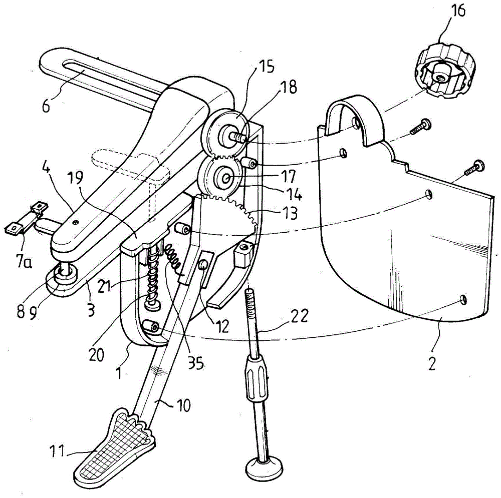
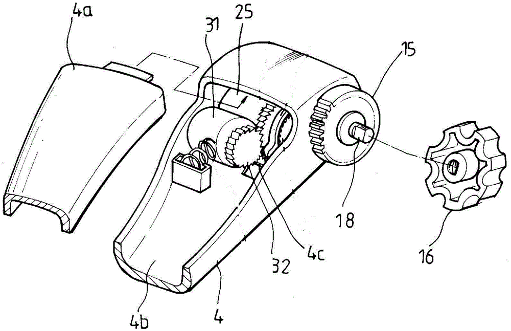
[0020] The reference signs in the drawings of the description include: rotating rod 10, pedal 11, hinge point 12, limit rod 22, teeth 13, rotating shaft 17, second gear 14, rotating gear 15, pin shaft 18, collar 6 , ear plate 7a, upper cover plate 19, connecting column 20, return spring 21, compression spring 35, support frame 1, side plate 2, gear cover 16, upper mold 8, lower mold 9, base plate 3, rotating cover plate 4, The upper plate 4a and the lower groove 4b.
[0021] The embodiment is basically as attached figure 1 As shown: the foot-controlled turning mechanism of this embodiment includes a rotating rod 10, a support frame 1, a bottom plate 3 and a rotating cover plate 4, the bottom plate 3 is fixed on the support frame 1, and the support frame 1 passes through figure 1 The lug 7a shown is secured with the collar 6 to other fixings.
[0022] One end of the rot...
PUM
 Abstract
Description
Claims
Application Information
 - R&D
- Intellectual Property
- Life Sciences
- Materials
- Tech Scout
- Unparalleled Data Quality
- Higher Quality Content
- 60% Fewer Hallucinations
Browse by: Latest US Patents, China's latest patents, Technical Efficacy Thesaurus, Application Domain, Technology Topic, Popular Technical Reports.
© 2025 PatSnap. All rights reserved.Legal|Privacy policy|Modern Slavery Act Transparency Statement|Sitemap|About US| Contact US: help@patsnap.com


