
Fault positioning method and device of communication network

A fault location and communication network technology, applied in the field of mobile communications, can solve the problems of low fault location accuracy and long time consumption

Active Publication Date: 2016-04-06
CHINA MOBILE GRP HENAN CO LTD
View PDF5 Cites 8 Cited by
  • Summary
  • Abstract
  • Description
  • Claims
  • Application Information

AI Technical Summary

Problems solved by technology

[0005] The embodiment of the present invention provides a communication network fault location method, which is used to solve the problem in the prior art that the fault location network element only performs fault analysis on the faulty network element that generates an alarm, and the fault location accuracy is low and takes a long time.

Method used


Image

  • Fault positioning method and device of communication network
  • Fault positioning method and device of communication network

Examples


Embodiment 1

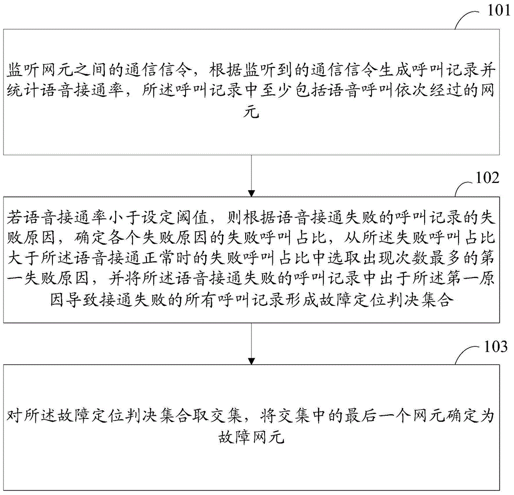
[0041] Such as figure 1 As shown, the embodiment of the present invention provides a communication network fault location method, including the following steps:

[0042] Step 101, monitoring the communication signaling between network elements, generating a call record according to the monitored communication signaling and counting the voice connection rate, the call record at least including the network elements that the voice call passes through in sequence;

[0043] Step 102, if the voice connection rate is less than the set threshold, then according to the failure reasons of the call records of voice connection failures, determine the proportion of failed calls for each failure reason, from the failure call proportion greater than the normal voice connection Select the first failure cause with the largest number of occurrences in the proportion of failed calls at that time, and form a fault location judgment set for all call records that cause connection failure for the fi...

Embodiment 2

[0113] The embodiment of the present invention also provides a device corresponding to the above method. For details of the device, please refer to the method part, which will not be repeated here.

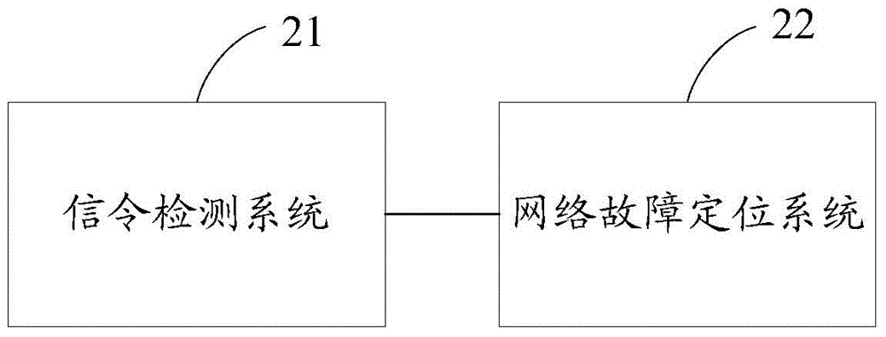
[0114] Such as figure 2 As shown, the communication network fault location device includes: a signaling detection system 21 and a network fault location system 22 .

[0115] Signaling detection system 21: used to monitor communication signaling between network elements, generate a call record according to the monitored communication signaling and count the voice connection rate, and the call record at least includes the network elements that the voice call passes through in sequence;

[0116] Network fault location system 22: used for if the voice connection rate is less than the set threshold, then according to the failure reasons of the call records of voice connection failures, determine the failure call ratio of each failure reason, from the failure call ratio greater than th...


PUM


Abstract

The invention discloses a fault positioning method and device of communication network. The method mainly comprises that communication signaling among network elements is monitored, call records are generated and the percent of completed voice calls is calculated according to the monitored communication signaling, and the call records comprise the network elements, which the voice call passes successively, at least; if the percent of completed voice call is lower than a set threshold, according to failure reasons of the call records in which voice connection fails, the proportions of failure calls caused by the different reasons are determined, the failure reason of the highest frequency is selected from the failure reasons, whose proportions of failure calls are greater than the proportion of failure calls in normal voice connection, as the first failure reason, and all calling records in connection failure caused by the first reason are selected from the calling records in voice connection failure to form fault positioning decision sets; and intersection sets are selected from the fault positioning decision set, and the last network element of the intersection sets is determined to be the fault network element. The method can be used to position the fault network element rapidly.

Description

technical field [0001] The present invention relates to the technical field of mobile communication, and in particular to a method and device for fault location of a communication network. Background technique [0002] With the growth of mobile users and the increase of business types, the number of communication network elements is also increasing, and the failure of communication network elements is also more frequent. After the occurrence of communication failures, analysis and location of failures are usually in the entire fault handling process. Taking up the most time, how to quickly locate faulty network elements, fault time, fault range, faulty services, and fault causes has become a key problem that the operation and maintenance department needs to solve, especially in the centralized operation and maintenance management mode, facing the needs of large-scale network elements more urgent. [0003] At present, the fault location is generally realized through the mass...

Claims


Application Information

Patent Timeline
IPC IPC(8): H04L12/26H04L12/24H04W24/04
Inventor 刘松波
Owner CHINA MOBILE GRP HENAN CO LTD
Learn More