Toggle-lever tension lock

A technology for locking devices and closing openings, applied in the direction of clamping devices, closing, packaging, etc., can solve problems such as clamping and locking device pollution, and achieve good cleaning effect

Active Publication Date: 2016-04-06
贡特拉姆·克雷泰克
View PDF6 Cites 18 Cited by
  • Summary
  • Abstract
  • Description
  • Claims
  • Application Information

AI Technical Summary

Problems solved by technology

Contamination of such clamping lock

Method used


Image

  • Toggle-lever tension lock
  • Toggle-lever tension lock
  • Toggle-lever tension lock

Examples


Embodiment Construction

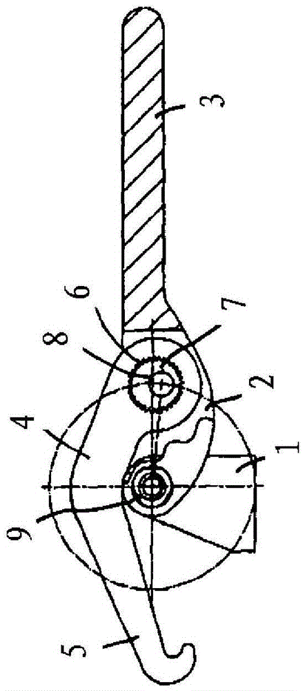
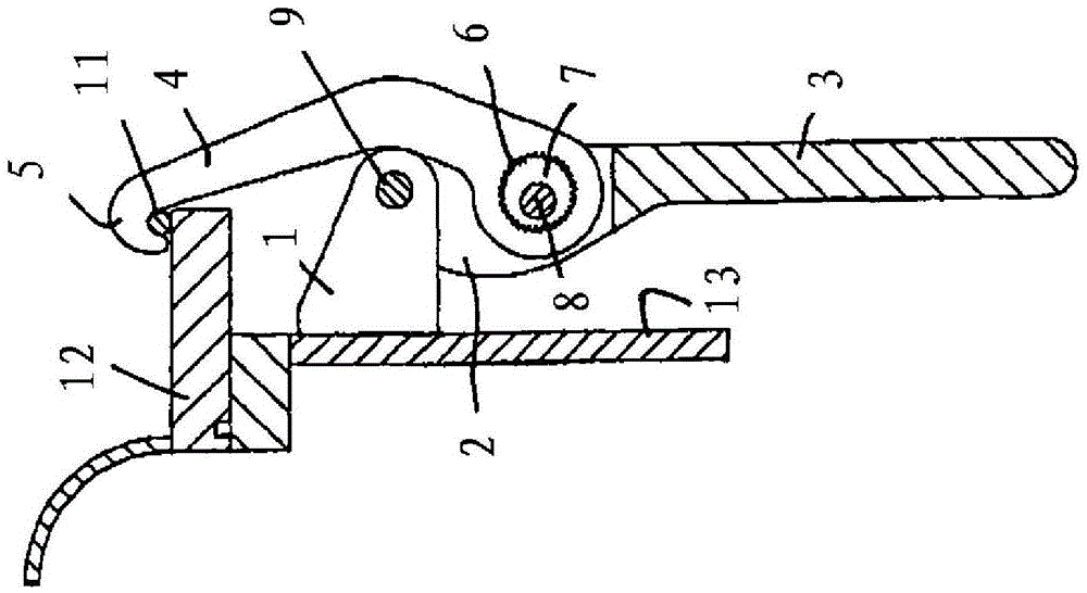
[0022] The clamping closure shown in the drawings comprises an approximately triangular base body 1 which can be fixedly or releasably arranged, for example, on a wall of a container and which forms a pivot for the clamping closure in its upper end region. Revolving bearing. The clamping lock also comprises a pivot element 2 which, in side view, has approximately the shape of an inverted triangle and has two triangular side sections and a connecting section. The two side sections of the pivot element 2 are pivotally mounted on the base body 1 , more precisely on the base body via a pivot pin or bearing pin 9 . The two side sections therefore surround the base body 1 on both sides.

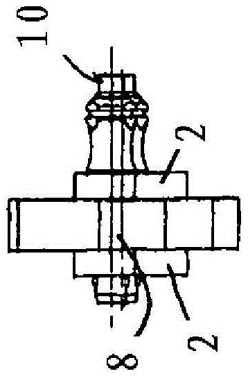
[0023] The pivot element 2 is also provided with a clamping lever 3 which is arranged on the connection section of the pivot element 2 . Furthermore, the pulling bow 4 is rotatably mounted on the pivot element 2 via a transverse pin 8 . The transverse pin 8 is mounted rotatably in two side secti...


PUM


Abstract

The invention relates to a tension lock for connecting a first component to a second component, in particular for connecting a cover (12) to a container (13), said cover closing an opening. To adjust the tension applied, the tension lock has an adjusting mechanism in the form of an internal eccentric bearing (6, 7) of a bearing pin (8) for a tensioning bow (4) of the tension lock. The tension lock, which can be dismantled into individual parts without the use of screws, offers good protection against contamination and can be cleaned particularly well. The tension lock is therefore particularly suitable for applications in the pharmaceutical industry or food industry.

Description

technical field [0001] The invention relates to a clamping closure for connecting a first component to a second component, in particular a lid closing an opening, to a container, the clamping closure comprising: Or a base body fixedly mounted on the first member; a pivot element with a clamping lever hingedly supported on the base body; a pulling bow rotatably supported on the pivot element, wherein the pulling bow The bearing position of the pivot element is adjustable with respect to the distance of the bearing position of the pivot element on the base body; and a corresponding holder for releasably or fixedly mounting the clamping locking device on the second member, pulling In the clamped state of the clamping lock, the bow engages behind the counter-holder. Background technique [0002] Clamping locks of this type are known. It works as follows: by manual operation of the clamping lever installed on the pivot element, the pivot element is rotated or deflected around t...

Claims


Application Information

Patent Timeline
IPC IPC(8): B65D45/24
CPCB65D45/24E05C19/14
Inventor 贡特拉姆·克雷泰克
Owner 贡特拉姆·克雷泰克
Why Eureka
Try Eureka