Bridge flexibility monitoring system based on visible light imaging technology

A bridge deflection and monitoring system technology, applied in the direction of measuring devices, optical devices, instruments, etc., can solve the problems of high manufacturing, installation and maintenance costs, complex calculations, complex optical system structures, etc., and achieve low operational difficulty and high precision , the effect of improving accuracy

Inactive Publication Date: 2016-04-13
CHENGDU SHANGJIA PHOTOELECTRIC TECH CO LTD
View PDF6 Cites 12 Cited by
  • Summary
  • Abstract
  • Description
  • Claims
  • Application Information

AI Technical Summary

Problems solved by technology

The main disadvantage of this patented technology is that the technical solution provided is limited to laser, and laser emitting and receiving devices are required. The structure of the optical system is complicated. At the same time, it needs to use a modem and complex calculations to solve the amplitude of the bridge. The calculation is too complicated and the system manufacturing , installation and maintenance costs are too high

Method used


Image

  • Bridge flexibility monitoring system based on visible light imaging technology
  • Bridge flexibility monitoring system based on visible light imaging technology
  • Bridge flexibility monitoring system based on visible light imaging technology

Examples


Embodiment 1

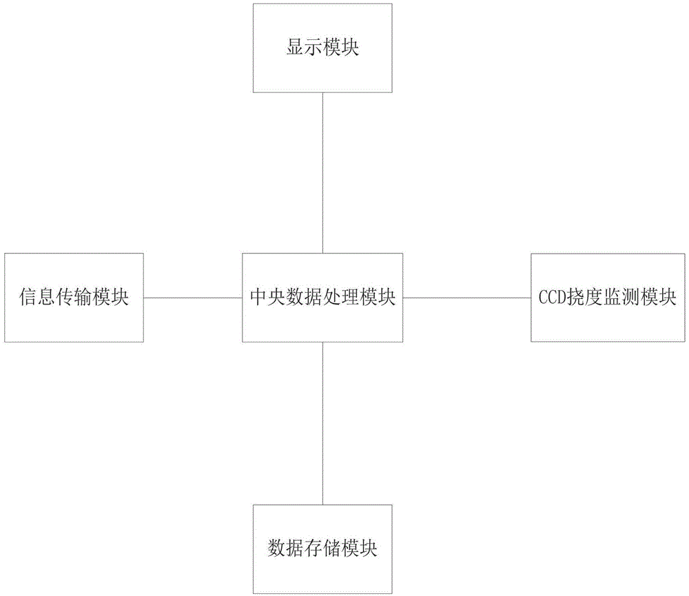
[0030] The deflection safety range of a certain bridge is N, and a vehicle passes the bridge deck. The CCD deflection monitoring module monitors that the deflection value of the vehicle is N1 and transmits the deflection to the central data processor. The central data processor determines that N1>N, The central data processing module invokes the alarm module to warn the vehicle exceeding the range of the deflection value according to the result of judging the deflection value monitored in real time, and at the same time identifies the license plate number and other information of the vehicle through the vehicle identifier, and the data storage module stores the event. The display module displays the judgment results, and the information transmission module transmits information such as the alarm and the license plate number of the vehicle involved in the accident to the road and bridge supervision center.

Embodiment 2

[0032] The deflection safety range of a certain bridge is N, and a vehicle passes the bridge deck. The CCD deflection monitoring module monitors that the deflection value of the vehicle is N2 and transmits the deflection to the central data processor. The central data processor determines that N>N2, The central data processing module requires the CCD deflection monitoring module to continue monitoring according to the result of judging the real-time monitoring deflection value.


PUM


Abstract

The invention discloses a bridge flexibility monitoring system based on the visible light imaging technology. The invention discloses a bridge flexibility monitoring system based on the visible light imaging technology, which is characterized by using a central data processing module to cooperatively work with a display module, an information transmission module, a data transmission module and a CCD flexibility monitoring module, using the non-contact monitoring mode, using the light as monitoring medium and using the CCD flexibility monitoring module which consists of a first stage processor, a CCD flexibility monitor, a CCD area array detector, an LED light source, an optical emission device, an optical reception device and a target to monitor whether the change of the flexibility value exceeds the flexibility limit. The invention replaces the laser with the visible light as a transmission medium, reflects change of flexibility of the bridge through the target reflection light spot displacement, does not need the complex operation, obtains the data change only through the image, and greatly reduces the system cost.

Description

technical field [0001] The invention relates to the field of bridge safety assessment, in particular to a bridge deflection monitoring system based on visible light imaging technology. Background technique [0002] With the rapid economic development, all kinds of bridges play an extremely important role in social life. The bridge is an important part of the transportation network. It plays an important role in the national economic life. Whether it can operate safely is directly related to the safety of the country and people's life and property. Among them, the deflection is one of the key parameters of bridge safety assessment, which has a great impact on the health of the bridge. The measurement of deflection is essential in the monitoring of bridge parameters. The safety risk of the bridge can be assessed by monitoring the change of deflection. [0003] At present, the existing technologies for monitoring bridge deflection are mainly divided into fiber grating sensor m...

Claims


Application Information

Patent Timeline
Patent Type & Authority Applications(China)
IPC IPC(8): G01B11/16
CPCG01B11/16
Inventor 卿光弼伍波
Owner CHENGDU SHANGJIA PHOTOELECTRIC TECH CO LTD
Why Eureka
Try Eureka