Emitter and emission device

A projectile and installation cavity technology, which is applied in the field of projectiles and launch devices, can solve the problems of reducing strike accuracy and projectiles are easily blocked by obstructions, so as to improve target range and accuracy, strike accuracy, and stability sexual effect

Inactive Publication Date: 2016-04-20
陈建宝
View PDF7 Cites 26 Cited by
  • Summary
  • Abstract
  • Description
  • Claims
  • Application Information

AI Technical Summary

Problems solved by technology

[0003] Therefore, the technical problem to be solved by the present invention is to overcome the technical defect that the emitter in the prior art is easily blocked by an obstruction and reduces the strike accuracy.

Method used


Image

  • Emitter and emission device
  • Emitter and emission device
  • Emitter and emission device

Examples


Embodiment 1

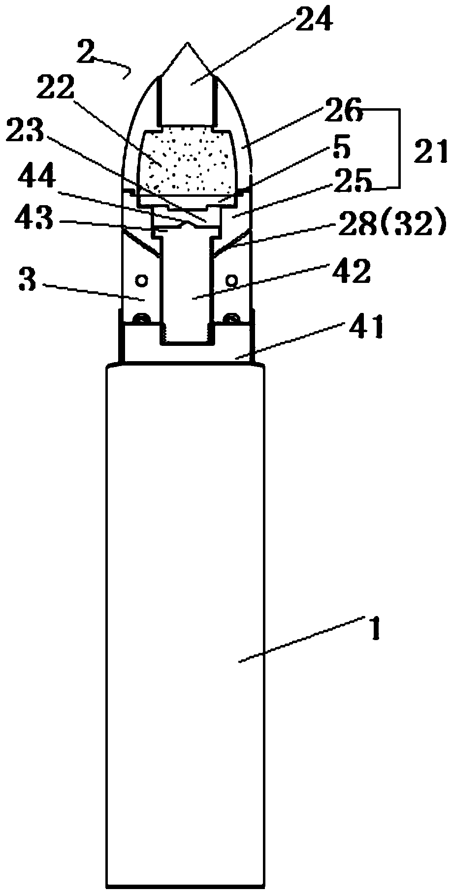
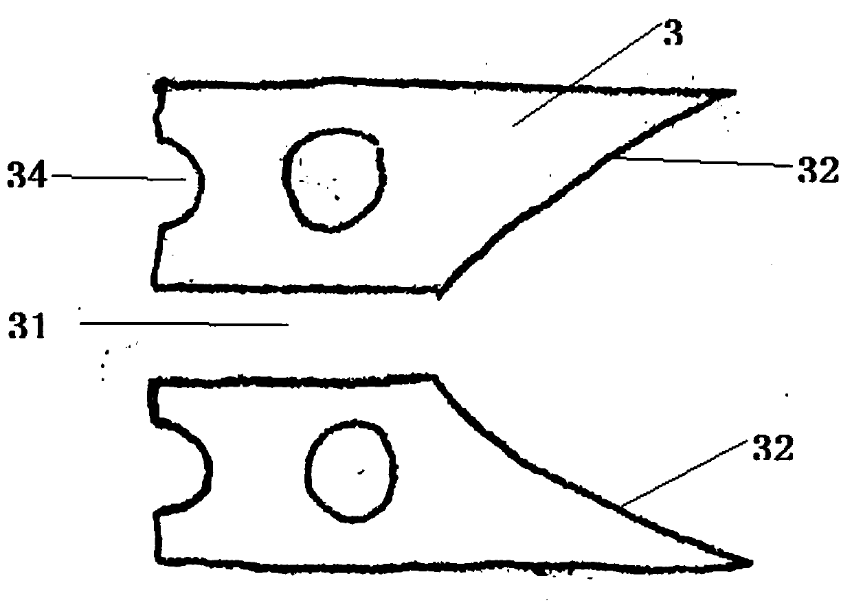
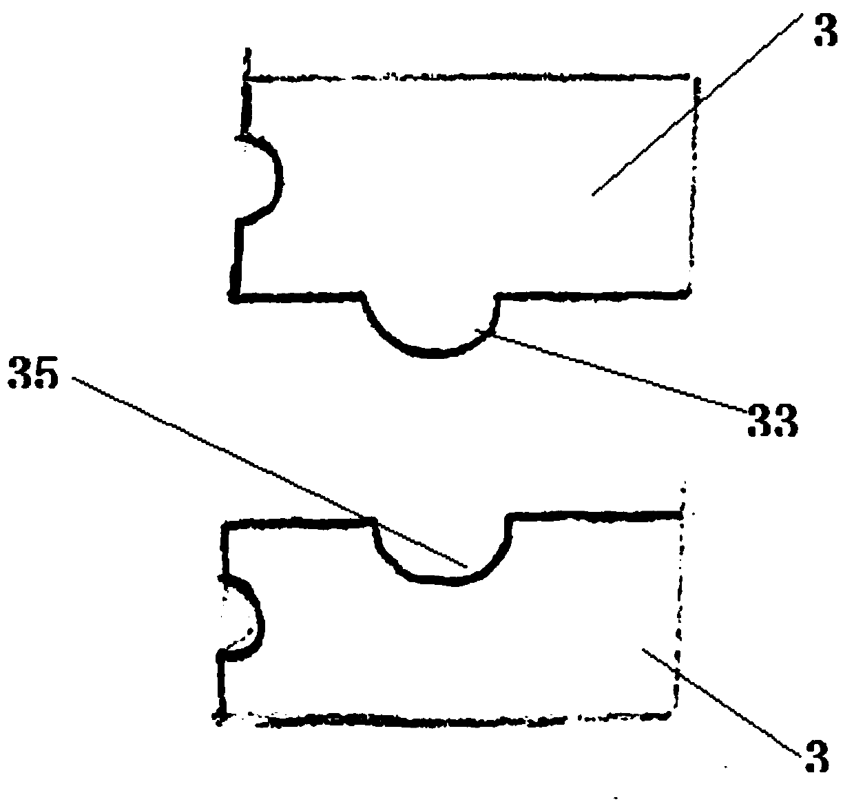
[0038] This embodiment provides a emitter, such as Figure 1-3 shown, including

[0039] cartridge case 1;

[0040] The warhead 2 is arranged on the front end of the projectile, and includes a bullet cap 21, and the bullet cap 21 is provided with a motive medium accommodation chamber 22 and an installation chamber and a channel 23 respectively communicated with the motive medium accommodation chamber 22, the installation chamber Located at the front end of the warhead 2, a cap head 24 is sealingly and movably connected to the installation cavity, and the motive medium accommodation cavity 22 is sealed and provided with a motive medium;

[0041] There are several movable blocks 3, which are provided with a cavity 31 communicating with the channel 23, and the several movable blocks 3 have a locked state that is connected for at least one circle in the circumferential direction and are integrated in the driving device 4. Driven to break the connection and disperse the unlocked ...

Embodiment 2

[0058] This embodiment provides an emission device, including a cavity, and an emitter located in the cavity, and the emitter is the emitter described in Embodiment 1. Because of having the projecting body, it has the advantages described in any one of the above. In particular, when the launching device is a toy pistol, since it can launch at multiple points, the interest is increased.

[0059] Preferably, the launching device is a toy pistol.


PUM


Abstract

The invention provides an emitter and an emission device. When a driving seat moves, a plurality of movable blocks are converted into an unlocking state from a locking state, and are dispersed around to form a dispersed and emitting effect, so that targets in a plurality of directions can be attacked and the attacking precision is improved; after the movable blocks are unlocked, the driving seat and a driving rod are unlocked; even if a bullet is blocked by an obstacle and stops running, the driving seat and the driving rod still move frontwards along a channel under the action of inertia, so that the front end of the driving rod stimulates a power medium and a cap head is emitted, and furthermore, continuous emission is carried out; a target range and precision of attacking are further improved.

Description

technical field [0001] The invention relates to an emitter and an emitter, belonging to the technical field of emitters. Background technique [0002] The projectile in the prior art mainly includes a cartridge case and a warhead. When the trigger is pulled, the warhead is excited to separate from the cartridge case and shoot out from the gun chamber to hit the target. If there is an obstruction in front of the target, after the projectile is fired from the barrel, since the warhead only runs in one direction, it is easy to be blocked by the obstruction, the speed decreases rapidly and stops running, and it is difficult to accurately strike the target through the obstruction. , reducing strike accuracy. Contents of the invention [0003] Therefore, the technical problem to be solved by the present invention is to overcome the technical defect in the prior art that the emitter is easily blocked by the shield and thus reduces the striking accuracy. [0004] For this reason...

Claims


Application Information

Patent Timeline
Patent Type & Authority Applications(China)
IPC IPC(8): A63H33/18A63F9/02
CPCA63F9/02A63F9/0252A63H33/18F42B12/02F42B12/72
Inventor 王海龙
Owner 陈建宝
Why Eureka
Try Eureka