An electrical maintenance toolbox

A technology for power maintenance and toolboxes, applied in the field of power maintenance toolboxes, can solve problems such as unsafe operation, waste of resources, single structure, etc., and achieve the effect of ensuring the safety of tools and facilitating the storage and transportation of structures

Active Publication Date: 2018-06-22
莘县鲁开综合服务有限公司
View PDF6 Cites 0 Cited by
  • Summary
  • Abstract
  • Description
  • Claims
  • Application Information

AI Technical Summary

Problems solved by technology

[0002] During the maintenance of electrical equipment, the toolbox carrying the tools usually has a single structure. During the maintenance, the staff need to use special equipment to detect whether someone has entered the fault area illegally, which is a waste of resources and at the same time, the operation is not safe.

Method used


Image

  • An electrical maintenance toolbox
  • An electrical maintenance toolbox

Examples


Embodiment 1

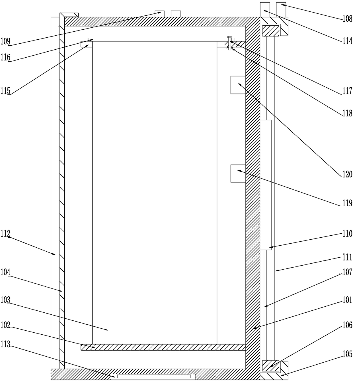
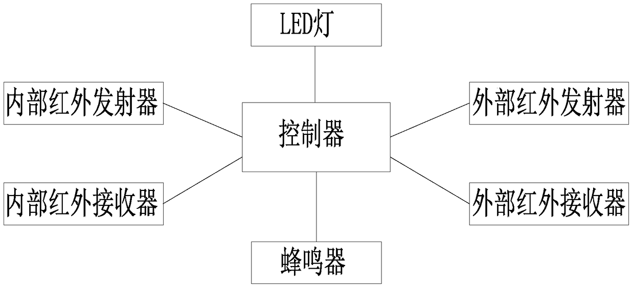
[0020] like figure 1 , 2 As shown, an electric power maintenance toolbox includes a toolbox body 101 and two fixing plates 102 respectively arranged at the upper and lower ends of the inside of the toolbox body 101, and a tool fixing plate 103 is arranged between the two fixing plates 102 , the toolbox body 101 is provided with an end cover 104, and the upper and lower ends of the toolbox body 101 away from the end cover 104 are respectively provided with chute 105, and the chute 105 is set There is a cross bar 106, the cross bar 106 can slide along the chute 105, two vertical bars 107 are connected at the ends of the two cross bars 106, and the two ends of the chute 105 are respectively provided with An external infrared transmitter 108 and an external infrared receiver 114 are provided with a controller inside the toolbox body 101, and the external infrared transmitter 108 and the external infrared receiver 114 communicate with the external infrared receiver 114 through lin...

Embodiment 2

[0023] In this embodiment, on the basis of Embodiment 1, in order to prevent the cross bar from falling out of the chute, in this embodiment, preferably, on the end surface of the tool box body 101 away from the side near the cross bar 106 A blocking portion 110 is provided, and a gear bar 111 is provided at the end of the two horizontal bars 106 away from the vertical bar 107 .

[0024] In this embodiment, in order to facilitate fixing the end cap structure, preferably, the end face of the tool box body 101 away from the cross bar 106 is bent inwardly to form a bent portion 112, and the end cap 104 snaps connected to the inner side of the bent portion 112 .


PUM


Abstract

The invention discloses an electric power overhauling toolbox, which comprises a toolbox body and two fixed plates arranged at the inner upper and lower ends of the toolbox body respectively, wherein a tool fixing plate is arranged between the two fixed plates; an end cover is arranged on the toolbox body; sliding chutes are formed in the upper and lower ends of the side, far away from the end cover, of the toolbox body respectively; cross rods are arranged in the sliding chutes, and can slide along the sliding chutes; vertical rods are connected to the tail ends of the two cross rods; external infrared transmitters and external infrared receivers are arranged at the two ends of the sliding chutes respectively; a controller is arranged on the inner side of the toolbox body; the external infrared transmitters and the external infrared receivers are connected with the controller through lines respectively. According to the electric power overhauling toolbox, the external infrared transmitters and the external infrared receivers are used for detecting whether a person enters a dangerous region from the outside or not, and an internal infrared transmitter and an internal infrared receiver are used for detecting whether a person illegally takes a tool or not.

Description

technical field [0001] The invention relates to an electric power maintenance tool box. Background technique [0002] During the maintenance of electrical equipment, the toolbox carrying the tools usually has a single structure. During the maintenance, the staff need to use special equipment to detect whether someone has entered the fault area illegally, which is a waste of resources and unsafe to operate. Contents of the invention [0003] The purpose of the present invention is to provide an electric maintenance toolbox, which can improve the problems existing in the prior art. By using an external infrared transmitter and an external infrared receiver, it is detected whether there is a person entering the dangerous area from the outside, and through the internal infrared transmitter and the external infrared receiver, The internal infrared receiver detects whether someone has taken tools illegally, making the whole operation safer during power maintenance. [0004] The...

Claims


Application Information

Patent Timeline
Patent Type & Authority Patents(China)
IPC IPC(8): B25H3/02G08B13/181
CPCB25H3/02G08B13/181
Inventor 不公告发明人
Owner 莘县鲁开综合服务有限公司
Why Eureka
Try Eureka