
Boom structure, construction machinery and measurement display table

A lifting arm and display meter technology, which is applied to cranes, measuring devices, power measurement, etc., can solve the problems of large changes in the lifting arm and difficulty in controlling the lifting moment, and achieve the effect of simplifying the control operation

Active Publication Date: 2017-03-01
ZOOMLION HEAVY IND CO LTD
View PDF6 Cites 0 Cited by
  • Summary
  • Abstract
  • Description
  • Claims
  • Application Information

AI Technical Summary

Problems solved by technology

[0005] The main purpose of the present invention is to provide a boom structure, a method for obtaining the lifting moment of the boom structure, engineering machinery and a measurement display table, so as to solve the problem of the lifting arm when the boom structure in the prior art is working. Large changes make it difficult to control the lifting moment

Method used


Image

  • Boom structure, construction machinery and measurement display table
  • Boom structure, construction machinery and measurement display table
  • Boom structure, construction machinery and measurement display table

Examples


Embodiment Construction

[0026] It should be noted that, in the case of no conflict, the embodiments in the present application and the features in the embodiments can be combined with each other. The present invention will be described in detail below with reference to the accompanying drawings and examples.

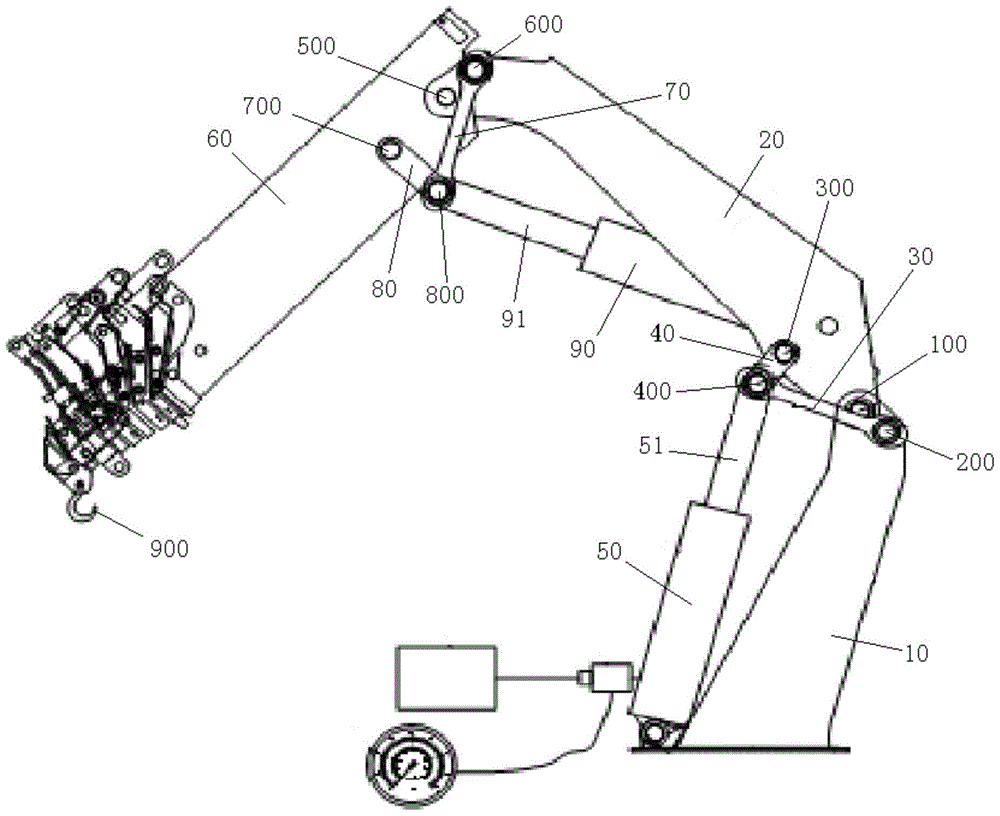
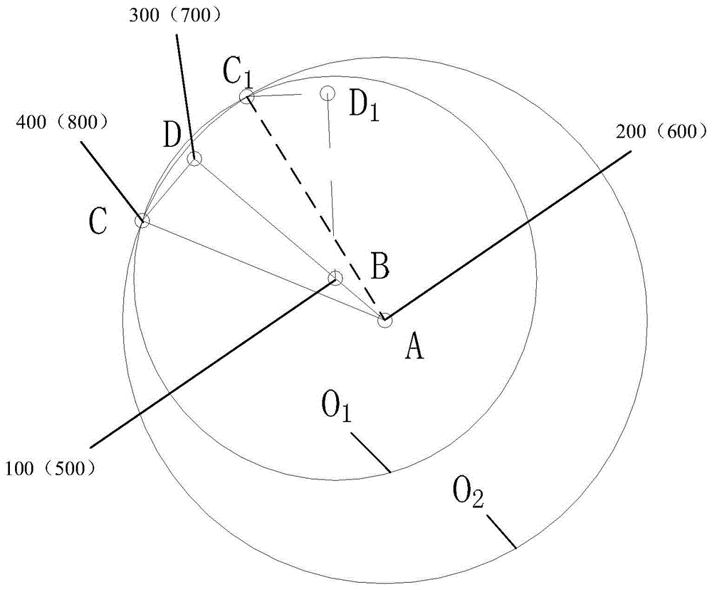
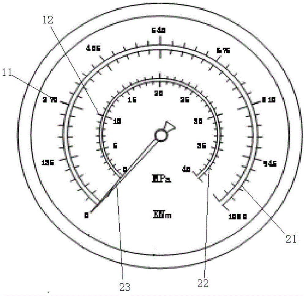
[0027] like figure 1 As shown, the boom structure of this embodiment includes a basic arm 10 , a first swing arm 20 , a first connecting rod 30 , a second connecting rod 40 and a first driving member 50 . Wherein, the first end of the first swing arm 20 is connected to the basic arm 10 through the first pivot 100 . The first end of the first link 30 is connected to the basic arm 10 through the second pivot 200 , and the second pivot 200 is located on the side of the first pivot 100 away from the first swing arm 20 . The first end of the second link 40 is connected to the first swing arm 20 through the third pivot 300, the third pivot 300 is located on the side of the first pivot 100 away from...


PUM


Abstract

The invention provides a boom structure, an acquisition method for the load moment of the boom structure, engineering machinery and a measuring display meter, wherein the boom structure comprises a base boom, a first swing arm, a first connecting rod, a second connecting rod and a first driving part; the first end of the first swing arm is connected to the base boom by a first pivot; the first end of the first connecting rod is connected to the base boom by a second pivot; the second pivot is located at one side, far away from the first swing arm, of the first pivot; the first end of the second connecting rod is connected to the first swing arm by a third pivot; the third pivot is located at one side, far away from the base boom, of the first pivot; the second end of the second connecting rod is connected together with the first end of the first connecting rod by a fourth pivot; the first driving part comprises a first push rod; and the end part of the first push rod is connected to the fourth pivot. The technical scheme provided by the invention solves the problems of the prior art that change of a lifting arm of force in work of the boom structure is large, and further the load moment is hard to control.

Description

technical field [0001] The invention relates to the technical field of construction machinery, in particular to a boom structure, a method for acquiring the lifting moment of the boom structure, construction machinery and a measurement display table. Background technique [0002] In the prior art, the method of controlling the lifting moment of engineering cranes including truck-mounted cranes is as follows: the length sensor and the angle sensor are used to measure the length and angle changes of the boom during movement, and at the same time, the pressure sensor measures the luffing cylinder. pressure. The actual lifting moment is calculated by the controller, and then compared with the set rated moment to avoid overloading, and the measured lifting moment or lifting capacity is displayed on the display. Since the lifting arm of the luffing cylinder varies greatly, under the same pressure of the luffing cylinder, the lifting moment applied to the jib is not equal at diffe...

Claims


Application Information

Patent Timeline
Patent Type & Authority Patents(China)
IPC IPC(8): B66C23/68B66C13/16G01L3/00
CPCB66C13/16B66C23/68G01L3/00
Inventor 周贤明陈亮
Owner ZOOMLION HEAVY IND CO LTD
Learn More