Path generation method and device

A path generation and path technology, applied in the direction of program control manipulators, manufacturing tools, manipulators, etc., can solve the problems of reducing the service life of equipment, not considering the turning angle, and sudden change of the joint angle of the equipment.

Active Publication Date: 2020-05-15
BEIJING C H L ROBOTICS CO LTD
View PDF16 Cites 0 Cited by
  • Summary
  • Abstract
  • Description
  • Claims
  • Application Information

AI Technical Summary

Problems solved by technology

[0004] Embodiments of the present invention provide a path generation method and device to at least solve the problem that the robot in the related art does not consider the turning angles between the edges of the trajectory in the trajectory path when generating the trajectory, which may easily cause sudden changes in the rotation of the joint angle of the equipment. Technical problems that reduce the service life of equipment

Method used


Image

  • Path generation method and device
  • Path generation method and device
  • Path generation method and device

Examples


Embodiment Construction

[0026] In order to enable those skilled in the art to better understand the solutions of the present invention, the following will clearly and completely describe the technical solutions in the embodiments of the present invention in conjunction with the drawings in the embodiments of the present invention. Obviously, the described embodiments are only It is an embodiment of a part of the present invention, but not all embodiments. Based on the embodiments of the present invention, all other embodiments obtained by persons of ordinary skill in the art without making creative efforts shall fall within the protection scope of the present invention.

[0027] It should be noted that the terms "first" and "second" in the description and claims of the present invention and the above drawings are used to distinguish similar objects, but not necessarily used to describe a specific sequence or sequence. It is to be understood that the data so used are interchangeable under appropriate ...


PUM


Abstract

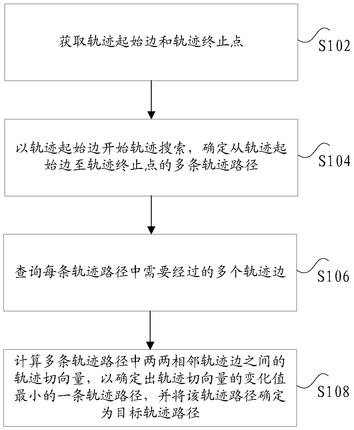
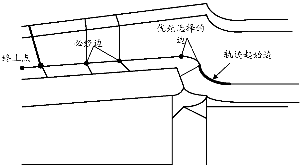
The invention discloses a path generation method and device. The method comprises the following steps: a trajectory initial edge and a trajectory stop point are obtained; a trajectory is searched fromthe trajectory initial edge to determine multiple trajectory paths from the trajectory initial edge and the trajectory stop point; multiple trajectory edges needing to be passed through are inquiredin each trajectory path; trajectory tangential quantities between every two adjacent trajectory edges in the multiple trajectory paths are calculated to determine the trajectory path with the lowest change value of the trajectory tangential quantities; and the trajectory path is determined as a target trajectory path. The method solves the technical problem of shortening of the equipment service life due to sudden change of equipment joint changes caused by no consideration of turning angles of all the trajectory edges in the trajectory paths during generating of the trajectories by a robot inrelated technologies.

Description

technical field [0001] The present invention relates to the field of equipment path processing, in particular, to a path generation method and device. Background technique [0002] In related technologies, when a robot performs a series of tasks such as welding, grinding, polishing, and calibration according to the trajectory line, it often needs to find an optimal trajectory path in advance to perform corresponding work along the trajectory path. When generating a trajectory, the trajectory path with the shortest path is often selected, and the turning angle between each trajectory edge in the trajectory path is not considered. This often results in a larger turning angle when the robot works, and the joint angle of the robot works The rotation angle tends to change suddenly, which will cause serious damage to the robot for a long time, reducing the service life of the robot, and the damage to the joint angle will make the maintenance of the robot difficult and waste a lot ...

Claims


Application Information

Patent Timeline
Patent Type & Authority Patents(China)
IPC IPC(8): B25J9/16
Inventor 刘昌森宋智广郭瑞军
Owner BEIJING C H L ROBOTICS CO LTD
Why Eureka
Try Eureka