
A rapid core making mechanism and rapid core making method

A fast, core box technology, applied in the direction of molding machines, manufacturing tools, casting molding equipment, etc., can solve the problems of not making full use of core making machines and reducing core making efficiency, so as to save core making equipment, improve core making efficiency, The effect of reducing the time of the empty loop

Active Publication Date: 2018-01-16
SUZHOU MINGZHI TECH
View PDF6 Cites 0 Cited by
  • Summary
  • Abstract
  • Description
  • Claims
  • Application Information

AI Technical Summary

Problems solved by technology

[0002] The core-making process usually includes the sand shooting process and the core blowing process. During the sand shooting, the air blowing / core pushing device moves to one side through the horizontal moving trolley, and the sand shooting mechanism moves to the center of the core box device through the horizontal moving trolley. The sand is shot from above. When blowing the core, the sand shooting mechanism moves to one side through the horizontal moving trolley, and the blowing / core ejecting device moves to the top of the core box device through the horizontal moving trolley to perform the blowing core. Each action The sum of the running time becomes the total running time of the equipment, which has more empty cycle time, which cannot make full use of the core making machine and reduces the core making efficiency

Method used


Image

  • A rapid core making mechanism and rapid core making method
  • A rapid core making mechanism and rapid core making method
  • A rapid core making mechanism and rapid core making method

Examples


Embodiment 1

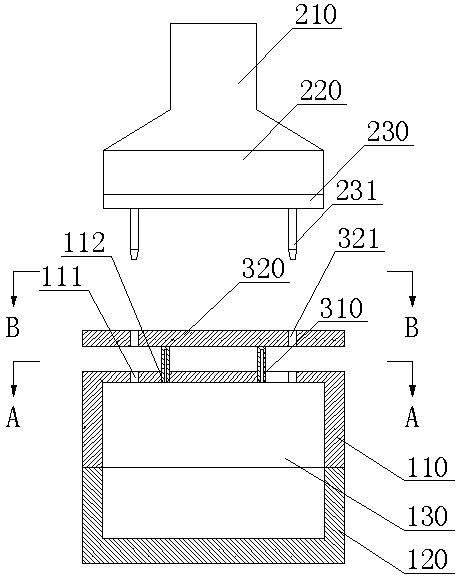
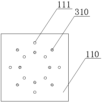
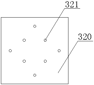
[0026] Embodiment one: see Figure 1-Figure 3 , as shown in the legend therein, is a rapid core-making mechanism, which includes a core box device, a sand shooting device and an air blowing / core ejecting device.

[0027] The above-mentioned core box device includes an upper core box 110 and a lower core box 120. The upper core box 110 has a core box top wall, and the core box top wall is provided with eight through-holes for sand shooting 111 and eight blowing / core holes. 112, eight sand shooting holes 111 and eight blowing / core holes 112 are set in a staggered manner.

[0028] The above-mentioned sand-shooting device includes a sand-shooting cylinder 210, a sand-shooting head 220 and a sand-shooting plate 230. The above-mentioned sand-shooting device is movable up and down above the top wall of the core box. The sand-shooting plate 230 is provided with eight sand-shooting holes. 111 correspond to eight sand nozzles 231 up and down.

[0029] The above-mentioned air blowing / c...

Embodiment 2

[0038] see Figure 4 to Figure 6 , as shown in the legend, the rest is the same as the first embodiment, the difference is that the rapid core making mechanism also includes a sealing plate 400, and the sealing plate 400 includes a through hole that passes through its upper and lower sides and matches the sand shooting nozzle 231. The hole 410 and the sealing plate 400 have the degree of freedom to rotate with the air blowing plate 320 on the horizontal plane. The through hole 410 and the avoidance hole 321 are completely staggered up and down or the through hole 410 and the escape hole 321 are completely connected up and down.

[0039] The above settings ensure that the mold cavity 130 remains in a sealed state when blowing and solidifying. There is also a transition step between step (3) and step (4). The transition step is as follows. Movement, the sand shooting nozzle 231 breaks away from the sand shooting hole 111 and the escape hole 321, and the sealing plate 400 rotates...

Embodiment 3

[0042] The rest is the same as the second embodiment, except that the above-mentioned sealing plate has a degree of freedom for translational movement with the above-mentioned blowing plate on the horizontal plane.


PUM


Abstract

The invention discloses a rapid core-making mechanism. The rapid core-making mechanism comprises a core box device, a sand-shooting device and a blowing / core-ejecting device, wherein sand-shooting holes and blowing / core-ejecting holes are arranged in the top wall of the core box; the sand-shooting holes and the blowing / core-ejecting holes are arranged in a staggered manner; the sand-shooting device is arranged above the top wall of the core box in a vertically moving manner and a sand-shooting plate is provided with sand-shooting nozzles; the blowing / core-ejecting device is fixedly arranged above the top wall of the core box and a blowing plate is provided with avoidance holes; blowing / core-ejecting rods penetrating through the blowing / core-ejecting holes are arranged on the lower side surface of the blowing plate; and the sand-shooting nozzles are located above the avoidance holes or sequentially penetrate through the avoidance holes and the sand-shooting holes. Through simultaneous arrangement for the sand-shooting holes and the blowing / core-ejecting holes in the top wall of the core box, and fixed arrangement for the blowing plate above the core box device, the blowing / core-ejecting device has no need to transversally move and vertically move, and the sand-shooting mechanism has no need to transversally move, thus the time of idle loops is reduced, the core-making efficiency is improved, and core-making equipment is omitted. The invention further provides a rapid core-making method.

Description

technical field [0001] The invention relates to the field of casting, in particular to a rapid core-making mechanism and a rapid core-making method. Background technique [0002] The core-making process usually includes the sand shooting process and the core blowing process. During the sand shooting, the air blowing / core pushing device moves to one side through the horizontal moving trolley, and the sand shooting mechanism moves to the core box device through the horizontal moving trolley. The sand is shot from the top. When blowing the core, the sand shooting mechanism moves to one side through the horizontal moving trolley, and the blowing / core ejecting device moves to the top of the core box device through the horizontal moving trolley to perform the blowing core. Each action The sum of the running time of the equipment becomes the total running time of the equipment, which has more empty cycle time, which cannot make full use of the core making machine and reduces the co...

Claims


Application Information

Patent Timeline
Patent Type & Authority Patents(China)
IPC IPC(8): B22C15/23
CPCB22C15/23
Inventor 陆高春李嘉
Owner SUZHOU MINGZHI TECH
Learn More