Lifting appliance for pneumatic wrench

A pneumatic wrench and spreader technology, applied in the direction of load hanging components, transportation and packaging, etc., can solve the problems of low assembly efficiency, safety hazards, waste of time, etc., and achieve the effect of easy safe pick-and-place and stable placement

Active Publication Date: 2016-04-27
BEIJING FOTONDAIMLER AUTOMOTIVE
View PDF5 Cites 2 Cited by
  • Summary
  • Abstract
  • Description
  • Claims
  • Application Information

AI Technical Summary

Problems solved by technology

[0002] In the related technology, the pneumatic wrench is placed on the material rack next to the work station, and employees need to go to the material rack to pick it up when using the pn

Method used


Image

  • Lifting appliance for pneumatic wrench
  • Lifting appliance for pneumatic wrench
  • Lifting appliance for pneumatic wrench

Examples


Example Embodiment

[0027] The embodiments of the present invention are described in detail below, and examples of the embodiments are shown in the accompanying drawings. The embodiments described below with reference to the accompanying drawings are exemplary, and are intended to explain the present invention, but should not be construed as limiting the present invention.

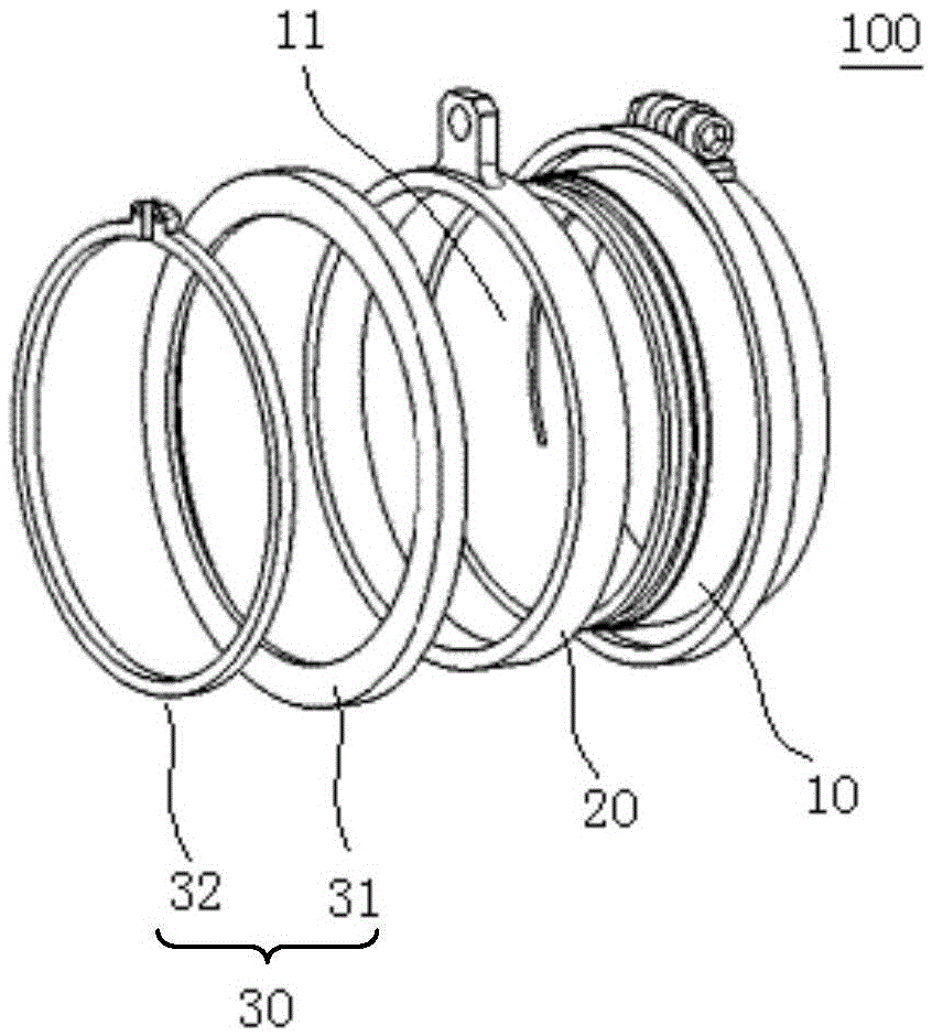
[0028] Refer below Figure 1 to Figure 7 The air wrench spreader 100 according to the embodiment of the present invention is described.

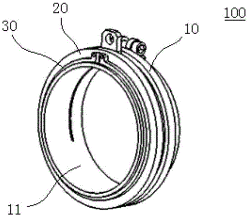
[0029] Such as figure 1 with figure 2 As shown, the sling 100 for a pneumatic wrench according to an embodiment of the present invention includes: a lifting ring 10, a rotating ring 20, and an axial limiter 30.

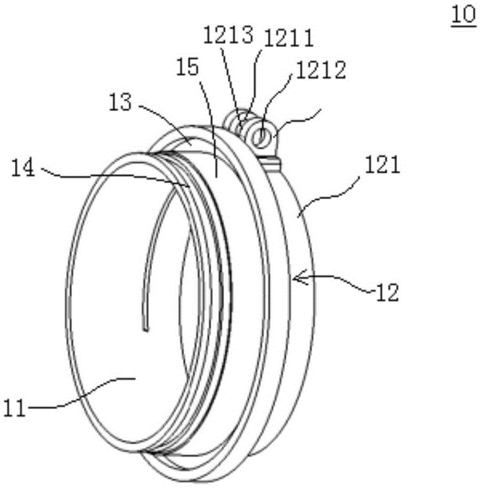
[0030] The lifting ring 10 has a mounting hole 11 for placing the pneumatic wrench and a locking portion 12 for locking the pneumatic wrench. The rotating ring 20 is sleeved outside the lifting ring 10 and can rotate relative to the lifting ring 10. The rotating ring 20 is provided wit...


PUM

PropertyMeasurementUnit
Central angleaaaaaaaaaa

Abstract

The invention discloses a lifting appliance for a pneumatic wrench. The lifting appliance comprises a lifting ring, a rotating ring and an axial limiting piece, wherein the lifting ring is provided with an installation hole where the pneumatic wrench is placed and a locking part for locking the pneumatic wrench; the rotating ring is arranged outside the lifting ring in a sleeving manner and can rotate relative to the lifting ring, and a lifting part is arranged on the rotating ring; and the axial limiting piece is arranged on the lifting ring in a sleeving manner, and the axial limiting piece and the lifting ring conduct axial limiting on the rotating ring jointly. According to the embodiment, the lifting appliance for the pneumatic wrench brings convenience to stable placement and safety taking and placing of the pneumatic wrench.

Description

technical field [0001] The invention relates to the technical field of tooling slings, in particular to a sling for a pneumatic wrench. Background technique [0002] In the related technology, the pneumatic wrench is placed on the material rack next to the work station, and the employees need to go to the material rack to get it when using the pneumatic wrench, which wastes time and reduces assembly efficiency. In addition, the pipeline of the pneumatic wrench is dragged randomly on the ground, which is likely to cause safety hazards. Contents of the invention [0003] The present invention aims to solve one of the technical problems in the related art at least to a certain extent. For this reason, the present invention proposes a spreader for an air wrench that facilitates the stable placement and safe pick-and-place of the air wrench. [0004] The air wrench hanger according to the embodiment of the present invention includes: a lifting ring, the lifting ring has a mou...

Claims


Application Information

Patent Timeline
IPC IPC(8): B66C1/10
CPCB66C1/10
Inventor 李志杰李云霄苑铁肖金陈炳
Owner BEIJING FOTONDAIMLER AUTOMOTIVE
Why Eureka
Try Eureka