A dual-wavelength test device suitable for determining the ignition delay time of a shock tube

A technology for ignition delay and time determination, which is applied in measurement devices, color/spectral characteristic measurement, and material analysis through optical means, and can solve the problems of high cost of grating monochromator, increased chassis size, and increased occupied space. , to achieve the effect of good shading performance, low manufacturing cost and convenient operation

Active Publication Date: 2018-06-22
WUHAN UNIV OF TECH
View PDF8 Cites 2 Cited by
  • Summary
  • Abstract
  • Description
  • Claims
  • Application Information

AI Technical Summary

Problems solved by technology

However, if it is necessary to increase the resolution of the grating monochromator and reduce the bandwidth of the monochromatic light emitted, it is necessary to use double gratings or increase its focal length, resulting in a significant increase in the size of the grating monochromator chassis, which in turn makes it occupy more space. surge
Moreover, in the actual operation process, the determination of the ignition delay time of the shock tube generally includes two methods: one is to measure the concentration signal of OH or CH* atomic groups on the side wall of a certain length from the end of the shock tube, and the other One is to measure the concentration signal of OH or CH* atomic groups on the blind end surface of the shock tube end. The data measured by these two methods are somewhat different. Due to the high cost of the grating monochromator, when simultaneous measurement When the concentration of OH and CH* atomic groups at the same position of the shock tube changes or the concentration of OH or CH* atomic groups at different positions of the shock tube changes, two grating monochromators must be used at the same time, which greatly increases the equipment cost

Method used


Image

  • A dual-wavelength test device suitable for determining the ignition delay time of a shock tube
  • A dual-wavelength test device suitable for determining the ignition delay time of a shock tube

Examples


Embodiment Construction

[0018] In order to facilitate those skilled in the art to understand and implement the present invention, the present invention will be described in further detail below in conjunction with the accompanying drawings and specific embodiments, but the present invention is not limited to the following embodiments.

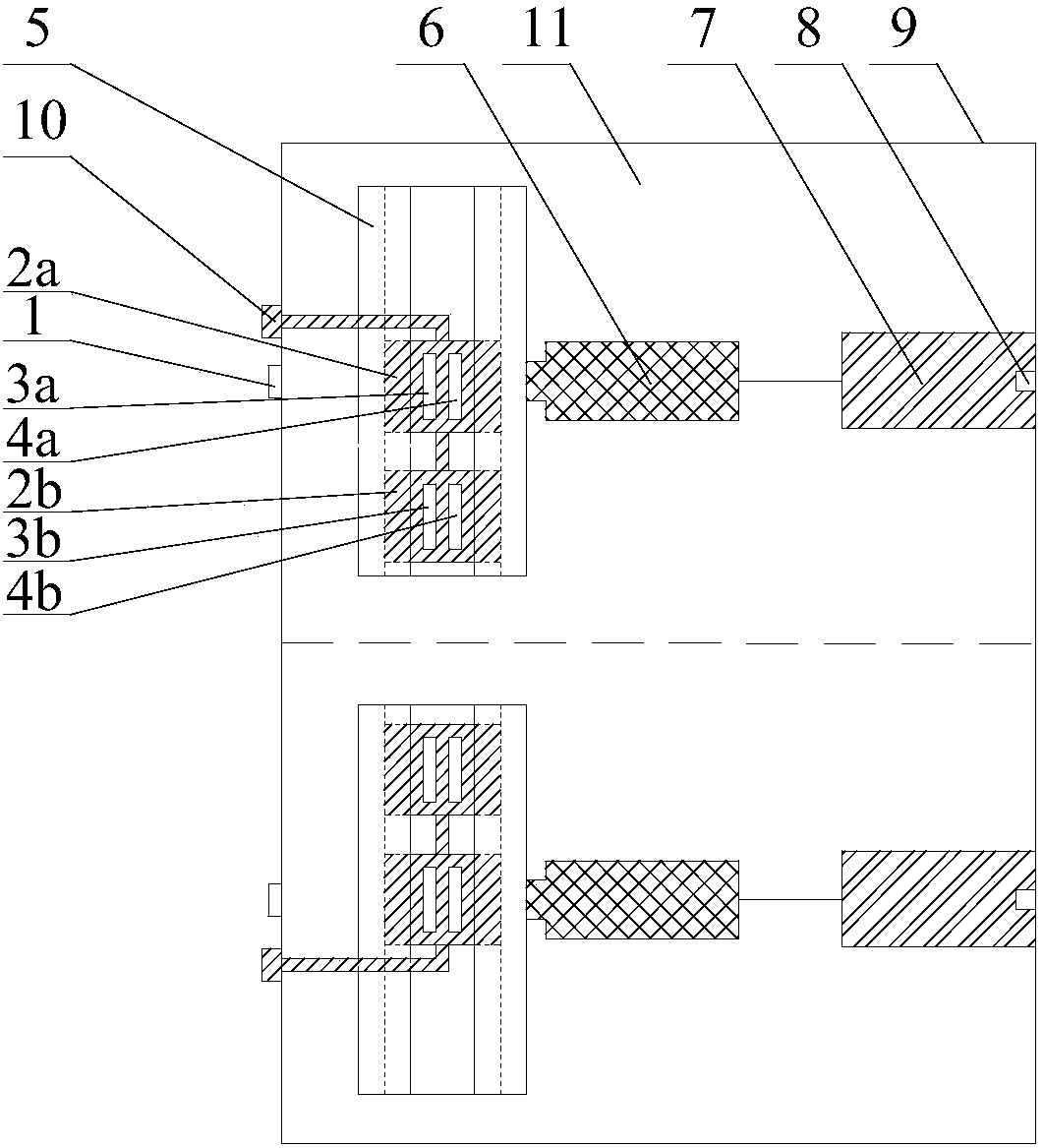
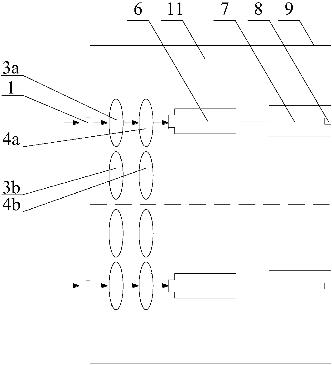
[0019] As shown in the figure, the dual-wavelength testing device of the present invention suitable for judging the ignition delay time of a shock tube includes a light-shielding cabinet 9, and inside the light-shielding cabinet 9, two sets of photoelectric conversion mechanisms 11 with the same structure are arranged side by side. Each photoelectric conversion mechanism 11 includes an optical fiber interface 1 installed on the side wall of the shading cabinet 9, a photomultiplier tube 6 installed inside the shading cabinet 9 opposite to the optical fiber interface 1, and a photomultiplier tube 6 installed between the optical fiber interface 1 and the photomultiplier tu...


PUM

PropertyMeasurementUnit
wavelengthaaaaaaaaaa

Abstract

The invention discloses a double-wavelength testing device applicable to the judgment of firing delay time of a shock tube. The double-wavelength testing device is composed of two sets of photoelectric conversion mechanisms with the same structure, wherein each photoelectric conversion mechanism comprises an optical fiber connector, a narrow band pass filter, a band pass filter, a photoelectric multiplier tube and an operational amplifying circuit; after compound light is introduced into the testing device, the light is filtered through the narrow band pass filters to form monochromatic light; when the monochromatic light penetrates through the band pass filters, stray light is further filtered; the filtered monochromatic light enters the photoelectric multiplier tubes and an optical signal is converted into an electric signal; and then the electric signal is processed by the operational amplifying circuits and is led out of the double-wavelength testing device. Each narrow band pass filter in the double-wavelength testing device comprises two sheets of filters with different central wavelengths and are changeable, and the measurement requirements on the concentration of OH or CH* atom radicals at different positions of the shock tube or the concentration of different atom radicals at the same position can be met; and the double-wavelength testing device is simple in structure, convenient to operate, low in manufacturing cost, convenient and firm to mount, good in light shielding performance and accurate and reliable in testing result.

Description

technical field [0001] The invention relates to a spectral intensity measuring device, in particular to a dual-wavelength testing device suitable for judging the ignition delay time of a shock wave tube. Background technique [0002] At present, the criteria used to determine the ignition delay time of the shock tube mainly include the change of pressure during the experiment and the change of the concentration of OH or CH* atomic groups. The existing shock tube OH and CH* atomic group concentration changes Most of the measurements use a combination of optical filters and photomultiplier tubes, or a combination of grating monochromators and photomultiplier tubes. [0003] When using optical filters and photomultiplier tubes for measurement, the optical filters and photomultiplier tubes that are close together must be fixed on the shock tube body, which is very inconvenient to place, and it is easy to be placed insecurely, which will affect the test At the same time, both si...

Claims


Application Information

Patent Timeline
Patent Type & Authority Patents(China)
IPC IPC(8): G01N21/31
CPCG01N21/31G01N2021/3129
Inventor 张尊华李敬瑞李格升
Owner WUHAN UNIV OF TECH
Why Eureka
Try Eureka