A grid reactive power control method, device and system
A control system and power grid technology, applied in reactive power compensation, emergency treatment AC circuit layout, AC network voltage adjustment, etc. Comprehensive reactive power demand and the effect of improving control efficiency
- Summary
- Abstract
- Description
- Claims
- Application Information
AI Technical Summary
Problems solved by technology
Method used
Image

Examples
Embodiment 1
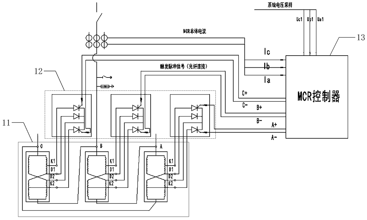
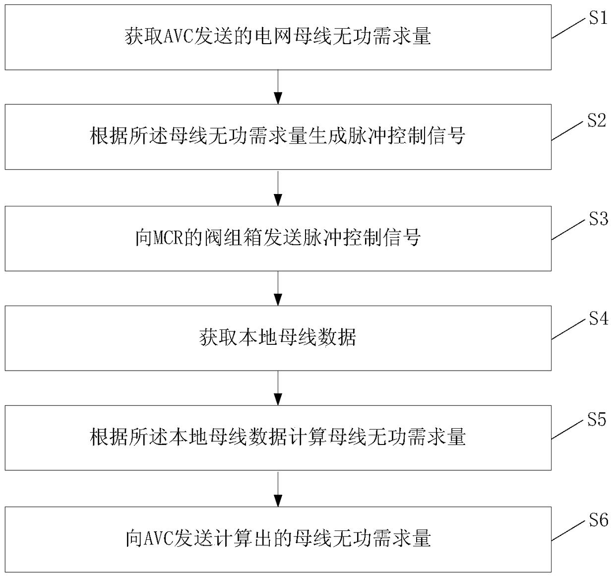
[0028] An embodiment of the present invention provides a grid reactive power control method, the method consists of figure 1 The magnetron reactor controller 13 in the system shown performs as figure 2 The method shown includes:
[0029] S1. Obtain the reactive power demand of the grid bus sent by the AVC system. The reactive power demand of the grid bus is the real-time bus data such as the bus voltage and reactive power of the entire network collected by the AVC system, and predicted by a specific algorithm before setting the target voltage. The bus reactive power that needs to be injected into the grid under the value. In actual use, the MCR controller can be connected with the AVC system, and the AVC system will automatically send the reactive power demand to the MCR controller.
[0030] S2, generating a pulse control signal according to the reactive power demand of the bus, that is, the frequency, current, voltage and other parameters of the control signal are calculat...
Embodiment 2
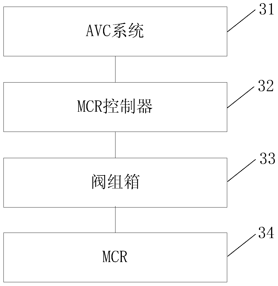
[0039] An embodiment of the present invention provides a grid reactive power control system, such as image 3 As shown, the system includes:
[0040] The AVC system 31 is used to collect grid bus data, and calculate the reactive power demand of the grid bus according to the bus data. The AVC system can collect the parameters of each node (substation at all levels), and calculate the reactive power of the whole network according to each node. Work demand;
[0041] The MCR controller 32 is connected with the AVC system, and is used to receive the reactive power demand of the grid bus, and generate a pulse control signal according to the reactive power demand of the grid bus;
[0042] Valve group box 33 and MCR34, the valve group box is connected with the MCR controller, the valve group box is used to receive the pulse control signal, and perform phase-shift trigger control on the MCR according to the pulse control signal To change the capacity of the MCR, the MCR outputs react...
Embodiment 3
[0047] The embodiment of the present invention provides another grid reactive power control system. The difference from the previous embodiment is that the MCR controller in this embodiment can also perform local closed-loop control and manual control, such as image 3 The system shown includes:
[0048] The AVC system 31 is used to collect grid bus data, and calculate the reactive power demand of the first bus according to the bus data, that is, the reactive power demand calculated according to the parameters of the whole network;
[0049] MCR controller 32, connected with the AVC system, is used to receive the reactive power demand of the first bus, and is also used to collect the local bus data, and calculate the reactive power demand of the second bus according to the local bus data (according to the local The reactive power demand calculated by the parameters) is also used to receive the control command input by the user, and generate a pulse control signal according to o...
PUM
 Abstract
Description
Claims
Application Information
 - R&D
- Intellectual Property
- Life Sciences
- Materials
- Tech Scout
- Unparalleled Data Quality
- Higher Quality Content
- 60% Fewer Hallucinations
Browse by: Latest US Patents, China's latest patents, Technical Efficacy Thesaurus, Application Domain, Technology Topic, Popular Technical Reports.
© 2025 PatSnap. All rights reserved.Legal|Privacy policy|Modern Slavery Act Transparency Statement|Sitemap|About US| Contact US: help@patsnap.com