Machining workbench device capable of adjusting angle

A technology of mechanical processing and workbench, which is applied in the direction of metal processing equipment, metal processing machinery parts, manufacturing tools, etc., can solve the problem of difficulty in meeting heavy load carrying requirements, increasing production line setting and operating costs, occupying a large area or space, etc. problems, to achieve the effect of improving mechanical stability, compact mechanical structure, and balanced drive layout

Inactive Publication Date: 2016-05-04
郑静
View PDF5 Cites 0 Cited by
  • Summary
  • Abstract
  • Description
  • Claims
  • Application Information

AI Technical Summary

Problems solved by technology

However, some existing angle adjustment methods are difficult to meet the load-bearing requirements of heavy loads during the adjustment process
Moreover, the drive device is often complex in structure and occupies a large area or space, which brings additional requirements for the installation of the processing line and the use of the factory building, and increases the production line setup and operating costs

Method used


Image

  • Machining workbench device capable of adjusting angle
  • Machining workbench device capable of adjusting angle
  • Machining workbench device capable of adjusting angle

Examples


Embodiment Construction

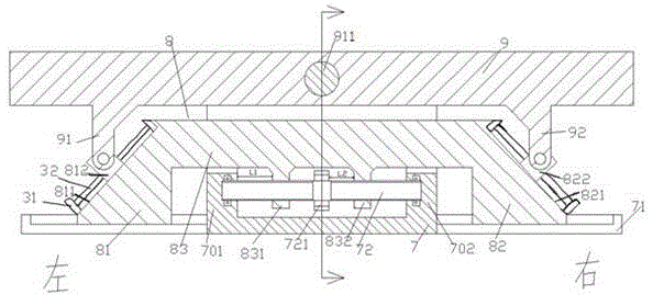
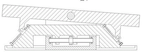
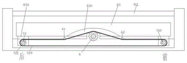
[0012] Combine below Figure 1-3 The present invention will be described in detail.

[0013] An angle-adjustable machining workbench device according to an embodiment includes a frame 7, a working platform part 9 hinged to the upper part of the frame 7 through a hinge shaft 911, and a work platform part 9 that can be fixedly arranged on the frame The angle adjustment support slider part 8 that slides left and right in the chute part 71 at the bottom of 7, wherein, the angle adjustment support slider part 8 includes a middle main body part 83 and two inclined parts 81, 82 symmetrically arranged left and right, The two slopes 81, 82 are respectively provided with mutually symmetrical slope slide grooves 811, 821 for sliding the left support slider 812 and the right support slider 822 respectively. The two slopes 81, 82 The upper and lower ends of the slope chutes 811, 821 are provided with installation blocks 31, and the guide rods 32 parallel to the slope chutes 811, 821 are f...


PUM


Abstract

A machining workbench device capable of adjusting the angle comprises a rack (7), a work platform part (9) hinged to the upper portion of the rack (7) through a hinging shaft (911), and an angle adjusting and supporting slider part (8) which can slide left and right in a slide groove part (71) fixedly arranged at the bottom of the rack (7), wherein the angle adjusting and supporting slider part (8) comprises a middle body part (83) and two bevel parts (81 and 82) which are bilaterally symmetrical. The two bevel parts (81 and 82) are provided with symmetrical bevel slide grooves (811 and 821) used for a left supporting slider (812) and a right supporting slider (822) to slide therein. The upper ends and the lower ends of the bevel slide grooves (811 and 821) of the two bevel parts (81 and 82) are both provided with installing blocks (31) which are internally and fixedly provided with guiding rods (32) parallel with the bevel slide grooves (811 and 821). The guiding rods penetrate the left supporting slider (812) and the right supporting slider (822), and the left supporting slider (812) and the right supporting slider (822) are hinged to supporting leg parts (91 and 92) symmetrically arranged at the left end and the right end of the lower side of the work platform part (9) respectively.

Description

technical field [0001] The invention relates to the field of workbenches of processing devices, in particular to an angle-adjustable machining workbench device. Background technique [0002] In the field of processing equipment, it is often necessary to use a workbench device to provide a platform for processing operations. In some processing fields, it is often necessary to process heavy workpieces and involve heavy processing execution equipment. This often makes the workbench need to carry a huge weight. [0003] Moreover, during the processing, the angle of the workbench needs to be adjusted adaptively, so as to meet the requirements of cooperation with other processing equipment during the processing. However, it is difficult for some existing angle adjustment methods to meet the requirements for carrying heavy loads during the adjustment process. Moreover, the drive device is often complex in structure and occupies a large area or space, which brings additional requ...

Claims


Application Information

Patent Timeline
Patent Type & Authority Applications(China)
IPC IPC(8): B23Q1/26
CPCB23Q1/265
Inventor 郑静
Owner 郑静
Why Eureka
Try Eureka