Bonding tooling for upper glass components that can be adjusted in size in any direction

A technology for adjusting size and arbitrary direction, applied in the direction of workpiece clamping device, manufacturing tools, etc., can solve the problems of low bonding efficiency, uneven bonding gap, easy misalignment, etc., and achieve high bonding efficiency and precision, bonding Fewer steps required and high bonding accuracy

Active Publication Date: 2017-04-26
NINGBO FOTILE KITCHEN WARE CO LTD
View PDF6 Cites 6 Cited by
  • Summary
  • Abstract
  • Description
  • Claims
  • Application Information

AI Technical Summary

Problems solved by technology

[0003] At present, there are mainly two methods to bond the bracket with the buckle to the back of the glass panel: one is the traditional bonding method, which uses manual bonding of the glass panel to the fan cover. This method has extremely low bonding efficiency. On the premise of increased labor costs, the processing cost has increased significantly, and because there is no pressure maintaining step, the bonding is not reliable, the glass panel is easy to detach from the front face of the smoke collection hood, and due to manual bonding, the bracket with buckle will be damaged. The bonding position is inaccurate and requires high technical skills for workers
The other is to use simple bonding tooling to bond the bracket with buckle. At present, the simple tooling has the following defects. One is that the size and position of the bonding are not easy to ensure the accuracy is low, and the positioning of the smoke hood and the glass panel Inaccurate, easy misalignment between the bracket with the buckle and the glass panel after bonding, and the bonding gap between the bracket with the buckle and the glass panel is uneven; the second is that the simple tooling is only suitable for one size of glass Bonding between the panel and the bracket with buckles has poor adaptability; thirdly, only one set of smoke collecting hoods can be bonded at a time, and the bonding efficiency is low

Method used


Image

  • Bonding tooling for upper glass components that can be adjusted in size in any direction
  • Bonding tooling for upper glass components that can be adjusted in size in any direction
  • Bonding tooling for upper glass components that can be adjusted in size in any direction

Examples


Embodiment Construction

[0030] The present invention will be further described in detail below in conjunction with the accompanying drawings and embodiments.

[0031] Such as Figure 1-13 Shown is a preferred embodiment of the present invention.

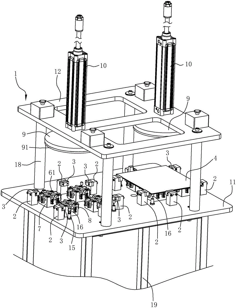
[0032] An upper glass component bonding tool that can be adjusted in size in any direction, such as Figure 13 As shown, the upper glass assembly of this embodiment includes a rectangular glass panel 4 and four buckle brackets 6 glued on the glass panel, each buckle bracket 6 has an adhesive surface 61 and a buckle 62 .

[0033] Specific bonding tooling includes

[0034] Such as figure 1 As shown, the frame body 1 has a table top 11 and an upper mounting plate 12 arranged at intervals up and down. The upper mounting plate 12 is located above the table top 11, and is supported by a column 18 between the table top 11 and the upper mounting plate 12. Below the table top 11 is provided 4 supporting feet 19 .

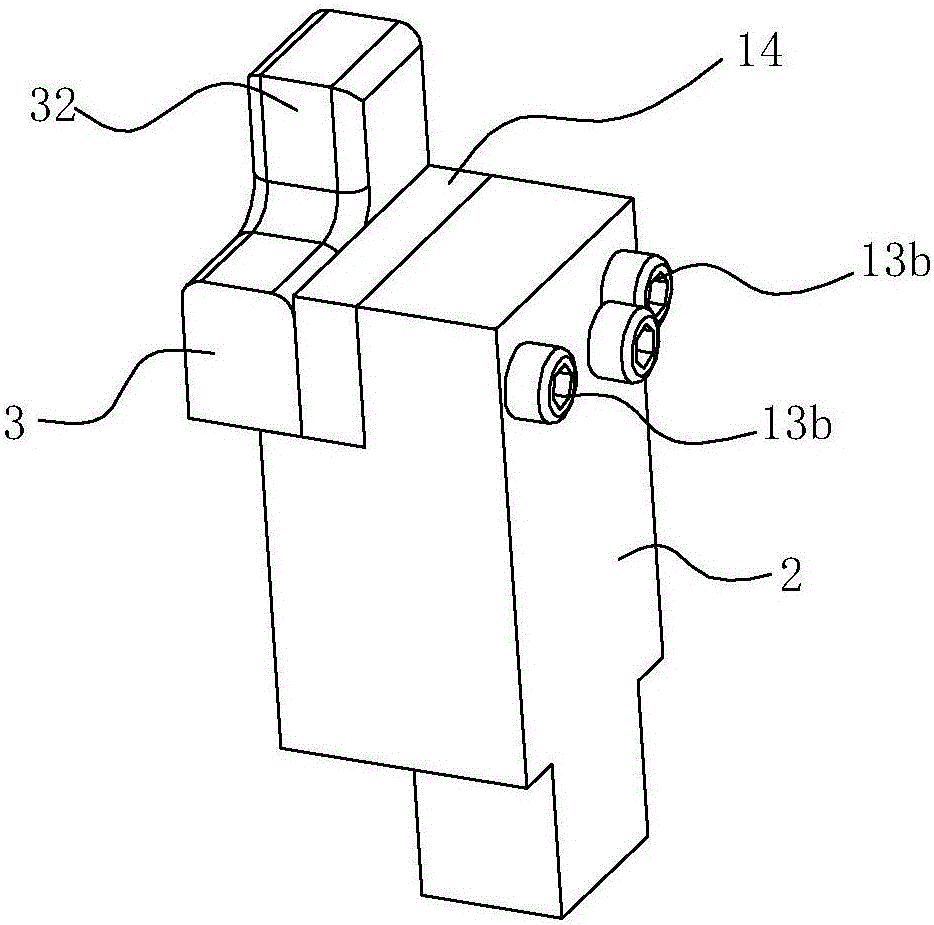
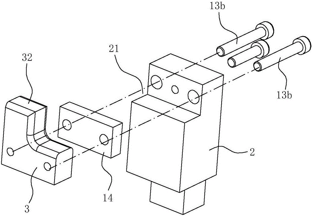
[0035] Such as Figure 3-8 As shown, the glass ...


PUM


Abstract

The invention relates to a bonding tool for mounting a part on a glass assembly and capable of adjusting dimensions in any direction. The bonding tool is characterized in that the tool comprises a rack body, glass panel limiting structures, support limiting structures and pressure maintaining blocks; the rack body is provided with a table board and an upper mounting plate; the glass panel limiting structures are used for limiting glass panels; the support limiting structures are used for limiting buckle supports; the pressure maintaining blocks are located above the glass panel limiting structures, and are driven by pressure maintaining cylinders mounted on the upper mounting plate to vertically move up and down; and the down pressing of the pressure maintaining blocks enables the glass panels to be tightly pressed on the bonding faces of the buckle supports to conduct pressure maintaining. In the bonding process, the relative position relation of the buckle supports and the glass panels is kept unchanged through the limiting of the glass panel limiting structures to the glass panels and the restraint of the support limiting structures to the buckle supports, and the bonding precision is high; the pressure maintaining blocks are driven by the action of the pressure maintaining cylinders to press the glass panels to the bonding faces, coated with glue, of the buckle supports and conduct pressure maintaining for a certain time, so that the buckle supports and the glass panels are firmly fixed.

Description

technical field [0001] The invention relates to a bonding tool for bonding a certain component to a glass panel, in particular to a bonding tool for an upper glass component whose size can be adjusted in any direction. Background technique [0002] In order to make the overall appearance of the range hood more beautiful and generous, glass panels are fixed on the surface of the shell parts of some high-end range hoods. Due to the particularity of the material, the bracket with the buckle needs to be fixed on the glass panel by bonding. [0003] At present, there are mainly two methods to bond the bracket with the buckle to the back of the glass panel: one is the traditional bonding method, which uses manual bonding of the glass panel to the fan cover. This method has extremely low bonding efficiency. On the premise of increased labor costs, the processing cost has increased significantly, and because there is no pressure maintaining step, the bonding is not reliable, the gl...

Claims


Application Information

Patent Timeline
Patent Type & Authority Patents(China)
IPC IPC(8): B25B11/00
CPCB25B11/00
Inventor 叶群茅忠群诸永定李立波
Owner NINGBO FOTILE KITCHEN WARE CO LTD
Why Eureka
Try Eureka