A wallpaper embossing and cutting device for automatic material collection
What is Al technical title?
Al technical title is built by PatSnap Al team. It summarizes the technical point description of the patent document.
An automatic material receiving and embossing technology, applied in thin material handling, transportation and packaging, mechanical processing/deformation, etc., can solve the problems of wasting manpower and material resources, low production efficiency, wasting time, etc., saving time and using high efficiency , the effect of improving work efficiency
Active Publication Date: 2018-12-14
WUJIANG WALLMATE DECORATION MATERIALS
View PDF6 Cites 0 Cited by
Summary
Abstract
Description
Claims
Application Information
AI Technical Summary
This helps you quickly interpret patents by identifying the three key elements:
Problems solved by technology
Method used
Benefits of technology
Problems solved by technology
[0003] In the production process of wallpaper, it is necessary to use a printing machine to emboss various patterns on its surface. The commonly used embossing device and principle are in the form of a rubber roller and a printing roller. The device pulls the wallpaper between the two rollers, and through the forward pressing of the rubber roller, the pattern on the embossing roller is embossed on the wallpaper. This method causes the production The efficiency is low and cannot meet the current production needs, and the wallpaper needs to be cut after embossing. If it is cut on another equipment, it will waste time and lower efficiency; and some equipment needs to manually collect the wallpaper, which is a waste of time. Manpower and material resources
Method used
Image
Click on the blue label to locate the original text in one second.
Reading with bidirectional positioning of images and text.
Examples
Embodiment Construction
[0014] Specific embodiments of the present invention will be further described in detail below.
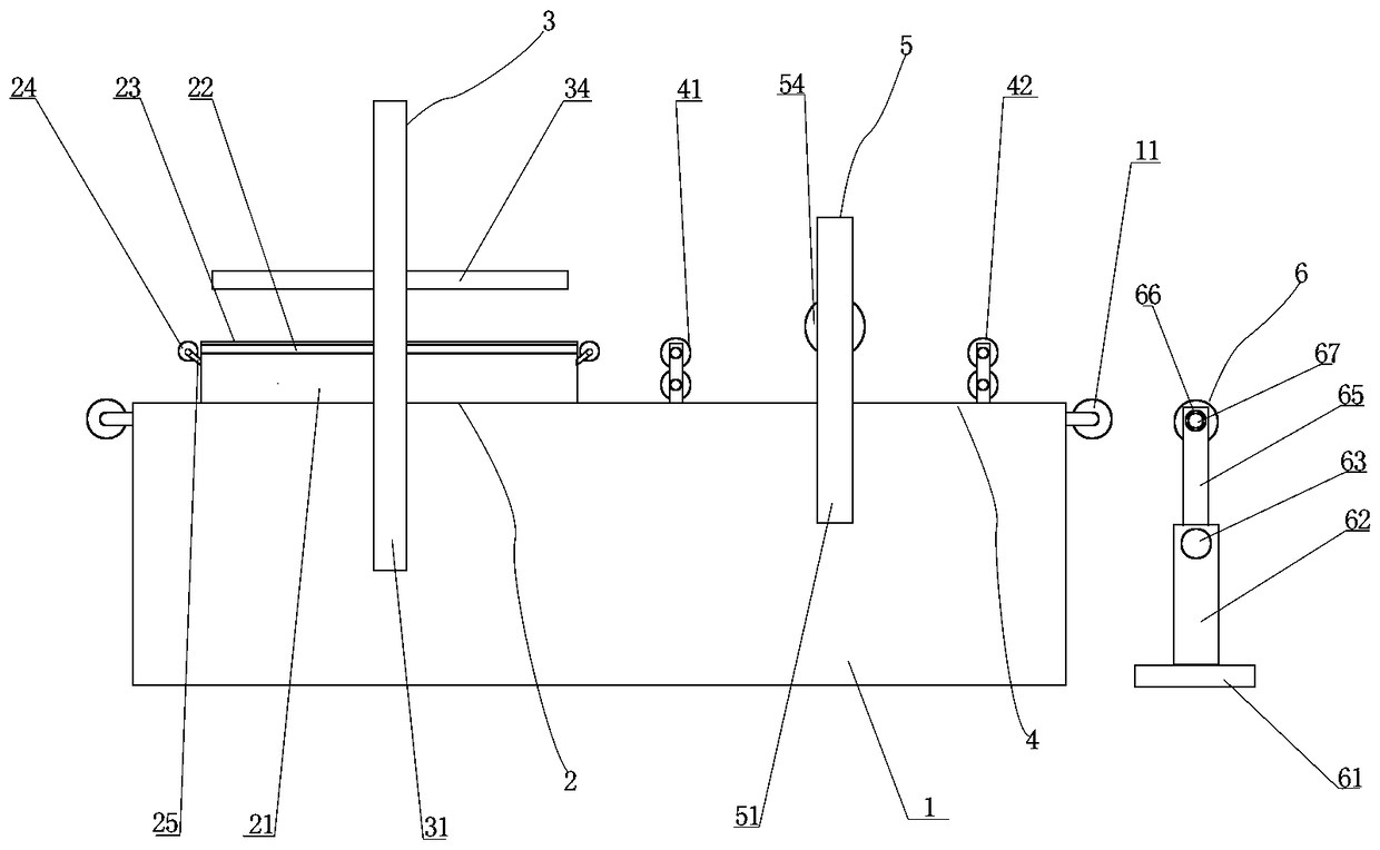
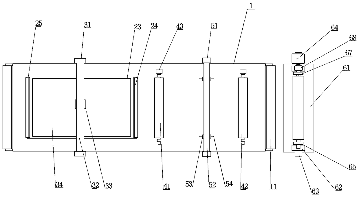
[0015] Such as figure 1 and figure 2 As shown, a kind of wallpaper embossing and cutting device of automatic material collection of the present invention, it comprises frame 1, is characterized in that: the top of frame 1 is respectively provided with embossing part 2 and the cutting part 4 of one side, embossing The flower part 2 includes a base 21 arranged on the top of the frame 1, a support plate 22 is horizontally arranged on the base 21, and first rollers 24 are arranged in parallel on both sides of the base 21, and the first roller 24 passes through two The connecting piece 25 at the end connects the base 21, the first roller 24 is as high as the support plate 22, the embossing part 2 also includes an embossing assembly 3 for wallpaper embossing arranged on the upper part of the frame 1, and the cutting part 4 includes The first double pressure roller 41 that is arranged...
PUM
Property
Measurement
Unit
thickness
aaaaa
aaaaa
Abstract
The invention discloses a wallpaper embossing and cutting device with an automatic collecting function. The wallpaper embossing and cutting device comprises a rack, wherein an embossing part and a cutting part on one side are respectively arranged on the top of the rack; the embossing part comprises a base arranged on the top of the rack; a supporting plate is horizontally arranged on the base; first rollers are respectively arranged on two sides of the base in parallel; the cutting part comprises a first double pressing roll arranged on the top of the rack; the first double pressing roll is parallel to the first rollers; a second double pressing roll is arranged on one side of the first double pressing roll in parallel; a collecting assembly is arranged on one side of the rack and comprises a horizontal support; two vertical plates are vertically arranged at two ends of the support respectively; a roll shaft is connected between top ends of the two vertical plates; a stepping motor is coaxially arranged at one end of the roll shaft; two connecting plates are respectively arranged at two ends of the roll shaft; the centers of the connecting plates are connected with the roll shaft; two shaft connectors are respectively arranged at two ends of each connecting plate; a connecting roll is detachably arranged between the two connecting plates; and a driving device is coaxially arranged at one end of each shaft connector.
Description
technical field [0001] The invention relates to the field of wallpaper processing, in particular to a wallpaper embossing and cutting device for automatic material collection. Background technique [0002] Wallpaper, also known as wallpaper, is an interior decoration material used to paste walls, and is widely used in interior decoration of houses, offices, hotels, hotels, etc. Because of its incomparable characteristics such as various colors, rich patterns, luxurious style, safety and environmental protection, convenient construction, and reasonable price, it has been popularized in developed countries and regions such as Europe, America, and Japan. Wallpapers are divided into many categories, such as laminated wallpapers, coated wallpapers, embossed wallpapers, etc. Usually bleached chemical wood pulp is used to produce base paper, and then processed by different processes, such as coating, printing, embossing or surface coating, and finally cut and packaged before leavi...
Claims
Application Information
Patent Timeline
Application Date:The date an application was filed.
Publication Date:The date a patent or application was officially published.
First Publication Date:The earliest publication date of a patent with the same application number.
Issue Date:Publication date of the patent grant document.
PCT Entry Date:The Entry date of PCT National Phase.
Estimated Expiry Date:The statutory expiry date of a patent right according to the Patent Law, and it is the longest term of protection that the patent right can achieve without the termination of the patent right due to other reasons(Term extension factor has been taken into account ).
Invalid Date:Actual expiry date is based on effective date or publication date of legal transaction data of invalid patent.