Attitude control engine vector thrust in-situ calibration device

An in-situ calibration, vector thrust technology, applied in the direction of measuring devices, force/torque/work measuring instrument calibration/testing, instruments, etc. Completely eliminate installation deformation and other problems, and achieve the effect of improving vector thrust measurement accuracy, light weight and simple structure

Active Publication Date: 2018-06-26
XIAN AEROSPACE PROPULSION TESTING TECHN INST
View PDF3 Cites 1 Cited by
  • Summary
  • Abstract
  • Description
  • Claims
  • Application Information

AI Technical Summary

Problems solved by technology

[0005] (2) During the vector thrust measurement process of the 2000N attitude control engine, the atmospheric pressure and ambient temperature are different from the calibration environment of the laboratory, resulting in a decrease in the accuracy of calculating the vector thrust of the engine using the calibration coefficient of the laboratory;
[0006] (3) During the vector thrust measurement process, the engine needs to supply propellant through the supply pipeline, and the installation of the pipeline cannot completely eliminate the installation deformation, which will inevitably produce a certain initial force value, and repeated installation of the pipeline is required for multiple tests. As a result, the initial force value is not exactly the same in each test process, and these states cannot be simulated in the laboratory;
[0007] (4) During the engine vector thrust measurement process, the supply pipeline will be deformed with the deformation of the vector force sensor, which will cause the thrust of the engine to be transmitted to the vector force sensor, and part of the force value will be lost due to the existence of the pipeline. Therefore, the force value measured by the vector force sensor is less than the true vector thrust of the engine
[0008] (5) At the same time, the existence of the supply pipeline will affect the mutual interference coefficient of the vector force sensor

Method used


Image

  • Attitude control engine vector thrust in-situ calibration device
  • Attitude control engine vector thrust in-situ calibration device
  • Attitude control engine vector thrust in-situ calibration device

Examples


Embodiment Construction

[0045] The present invention will be further described below in conjunction with accompanying drawing:

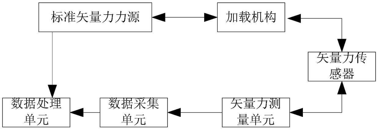
[0046] Such as figure 1 As shown, the attitude control engine vector thrust in-situ calibration device includes a standard vector force source, a loading mechanism, a vector force measurement unit, a data acquisition unit and a data processing module.

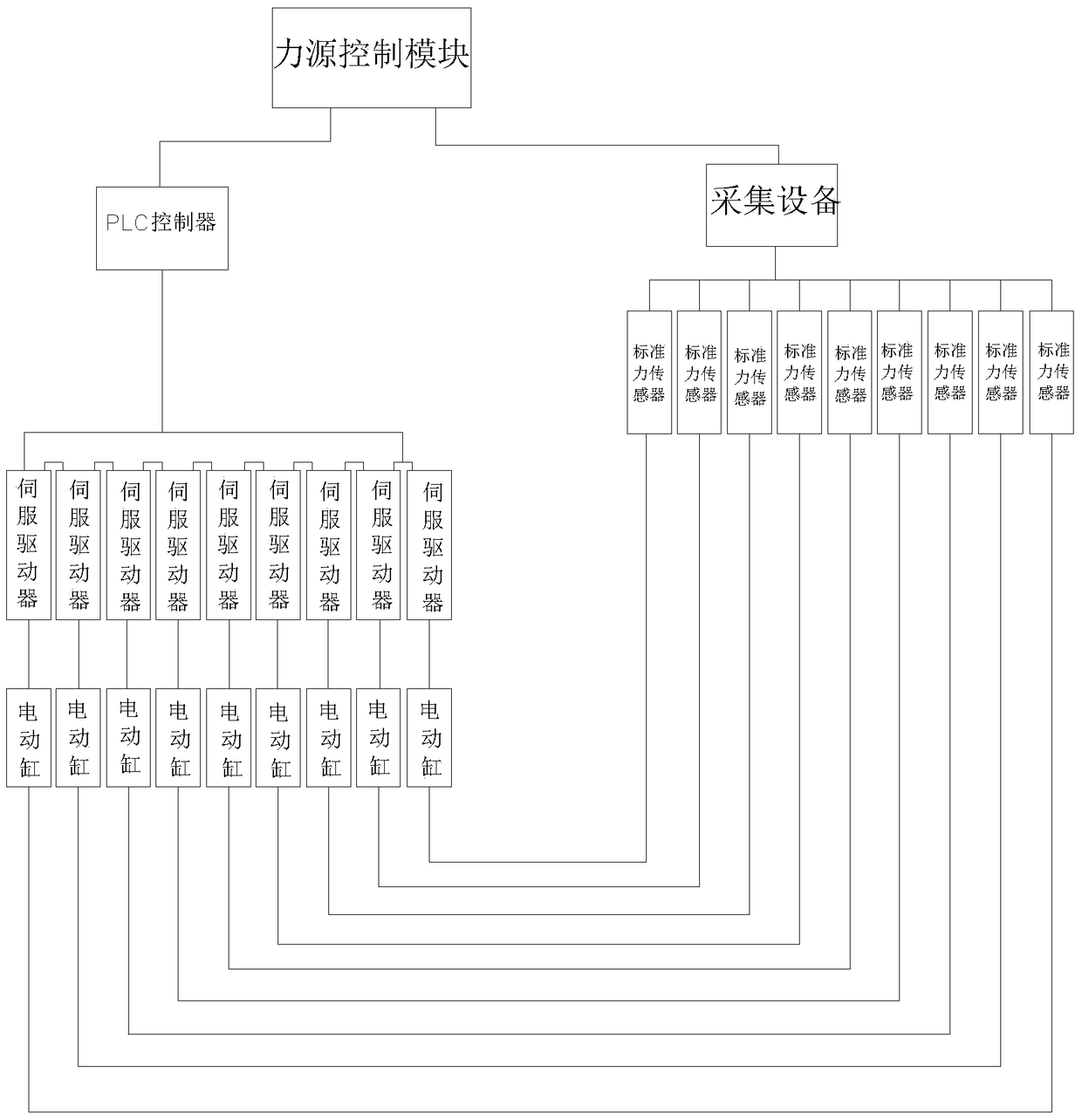
[0047] The standard vector force source is used to generate and control 9 standard forces to act on the loading mechanism according to the execution requirements;

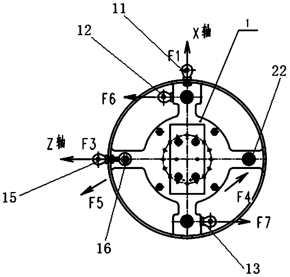
[0048] The loading mechanism is used to fix the vector force sensor to be calibrated, and apply 9 standard forces in different places to complete the force loads Fx, Fy, Fz in three directions of the vector force sensor to be calibrated and the moment loads in three directions Mx, My, Mz loading;

[0049] The vector force measurement unit is used to collect the voltage signal output by the vector force sensor to be calibrated and store it in the data processing...


PUM


Abstract

The invention relates to an attitude control engine vector thrust original position calibration apparatus. The apparatus comprises a standard vector force source, a loading mechanism, a vector force measurement unit, a data acquisition unit and a data processing unit, wherein the standard vector force source is used for generating and controlling nine standard force to act on the loading mechanism according to an execution requirement; the loading mechanism is used for fixing a vector force sensor to be calibrated; the vector force measurement unit is used for acquiring voltage signals output by the vector force sensor to be calibrated and storing the voltage signals to the data processing module; and the data processing module is used for receiving a loading result from the standard vector force source and a measurement result from the vector force measurement unit, and after storage comparison, obtaining a calibration coefficient of the vector force sensor to be calibrated. The attitude control engine vector thrust original position calibration apparatus can be remotely automatically calibrated in a 2Pa high-modulus environment, can effectively eliminate the influence of a propellant supply pipeline and a measurement cable on vector thrust measurement and improves the vector thrust measurement precision.

Description

technical field [0001] The invention relates to an aerospace engine test, in particular to a test method for in-situ calibration of a vector thrust measuring device before and after an attitude control engine high-altitude simulation test. Background technique [0002] Ideally, the thrust of the engine coincides with the central axis of the engine, but the actual situation is often: due to the limitation of machining accuracy and the influence of asymmetric factors, the geometric asymmetry of the engine is formed, or the gap between the engine throat and the nozzle is formed under high temperature and high pressure. The deformation and the asymmetric flow of gas in the nozzle cause the thrust action line of the engine to deviate from the central axis of the engine, resulting in thrust eccentricity, lateral thrust and the moment of the main thrust vector around the center of mass of the propeller. To solve these problems, in a certain model 2000N During the engine development...

Claims


Application Information

Patent Timeline
Patent Type & Authority Patents(China)
IPC IPC(8): G01L25/00
CPCG01L25/00
Inventor 李广会冷海峰周晶刘丽宁王宏亮李志勋黄鹏辉田健江
Owner XIAN AEROSPACE PROPULSION TESTING TECHN INST
Why Eureka
Try Eureka