Hydrogen elimination system of nuclear power plant concrete containment

A nuclear power plant containment and containment technology, which is applied in power plant safety devices, nuclear power generation, nuclear engineering, etc., can solve the problems of hydrogen elimination scheme safety hazards, safety hazards not completely eliminated, scheme design defects, etc., to eliminate hydrogen explosions risk, eliminate the risk of system failure, and overcome the effect of low reliability

Active Publication Date: 2016-05-04
中广核工程有限公司 +1
View PDF8 Cites 3 Cited by
  • Summary
  • Abstract
  • Description
  • Claims
  • Application Information

AI Technical Summary

Problems solved by technology

[0007] 1) Passive defect: when the concentration of hydrogen reaches the deflagration concentration, the system will send out an alarm signal; if hydrogen accumulates rapidly in the containment at this time, during the period from when the operator gets the information to taking action, the The risk of hydrogen explosion is very high. Therefore, the passive hydrogen elimination scheme itself has potential safety hazards;
[0008] 2) Defects of the manual type: Since the third-generation nuclear power plants are required to consider human error, at least 30 minutes should be kept without operator intervention. In the manual type scheme, the hydrogen elimination action needs to be manually started by the operator. If you start or fail to start the hydrogen elimination action in time, the system will fail, and the consequences will be very serious!
[0009] It can be seen that there are deficiencies in the existing hydrogen elimination schemes, especially for the hydrogen elimination schemes under the normal operation of nuclear power plants or design basis accident conditions, or the economic cost is high and the reliability is not high, or the scheme design has defects, and All are passive solutions, resulting in safety hazards that have not been completely eliminated

Method used


Image

  • Hydrogen elimination system of nuclear power plant concrete containment
  • Hydrogen elimination system of nuclear power plant concrete containment
  • Hydrogen elimination system of nuclear power plant concrete containment

Examples


Embodiment Construction

[0034] In order to make the purpose of the invention, technical solution and beneficial technical effects of the present invention clearer, the present invention will be further described in detail below in conjunction with the accompanying drawings and specific implementation methods. It should be understood that the specific implementations described in this specification are only for explaining the present invention, not for limiting the present invention.

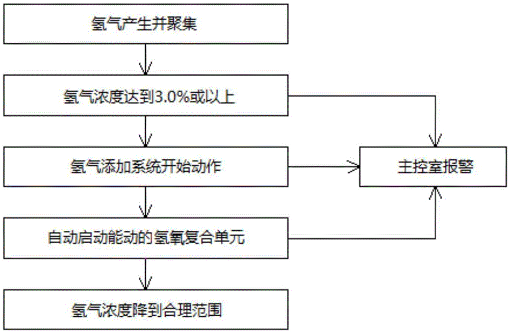
[0035] see image 3 and Figure 4 As shown, the nuclear power plant containment hydrogen elimination system of the present invention includes: a hydrogen monitoring subsystem, an automatic hydrogen addition subsystem, and an automatic hydrogen-oxygen recombination subsystem.

[0036] The hydrogen monitoring subsystem includes two redundant monitoring series, one for standby and one for use, each monitoring series includes five sensors 100 for monitoring the hydrogen content in the containment vessel 10 and an instrumen...


PUM


Abstract

The invention discloses a hydrogen elimination system of a nuclear power plant concrete containment. The system comprises the following parts: a hydrogen monitoring subsystem, which is for monitoring the concentration of hydrogen inside the concrete containment and sending an alarm signal when the hydrogen content reaches or exceeds a preset alarm value; an automatic hydrogen addition subsystem, which is for receiving the alarm signal from the hydrogen monitoring subsystem, adding hydrogen into an automatic hydrogen-oxygen recombination subsystem according to the alarm signal and sending an ignition signal; and the automatic hydrogen-oxygen recombination subsystem, which is for receiving the ignition signal and the added hydrogen from the automatic hydrogen addition subsystem, preparing for hydrogen-oxygen recombination according to the ignition signal, and reducing the hydrogen content in the concrete containment when the hydrogen content reaches blasting concentration through the controlled combustion. Compared with the prior art, the system automatically carries out elimination of hydrogen, controls the hydrogen content in the concrete containment in a safe range under the conditions of normal operation and basis accident, so as to avoid hydrogen blasting accident.

Description

technical field [0001] The invention belongs to the field of nuclear reactor design, more specifically, the invention relates to a containment hydrogen elimination system of a nuclear power plant that can automatically and actively eliminate hydrogen under normal operation and reference accidents. Background technique [0002] Under the normal operation of nuclear power plant reactors and design basis accidents, a certain amount of hydrogen will be produced in the containment vessel, which will eventually accumulate in the dome area of ​​the containment vessel. When the concentration of hydrogen reaches a certain level (for example, the volume concentration is above 4%), there will be a risk of explosion, which will bring serious safety hazards to the reactor building and even the entire nuclear power plant. Therefore, a reliable method must be adopted to strictly control the hydrogen content in the containment to eliminate safety threats. [0003] The risk of explosion cau...

Claims


Application Information

Patent Timeline
Patent Type & Authority Applications(China)
IPC IPC(8): G21C9/00G21D3/06
CPCG21C9/001G21D3/06Y02E30/00Y02E30/30
Inventor 叶镕刘永赵亮吴春明程浩何炜亭叶子青周媛霞侯淑娟
Owner 中广核工程有限公司
Why Eureka
Try Eureka