
Cutting elements, related methods of forming a cutting element, and related earth-boring tools

A cutting element and cutting surface technology, which is applied in the manufacture of tools, earthwork drilling, drill bits, etc., can solve the problems of uneven leaching depth of PDC, defective cutting elements, etc.

Active Publication Date: 2016-05-04
BAKER HUGHES HLDG LLC
View PDF9 Cites 2 Cited by
  • Summary
  • Abstract
  • Description
  • Claims
  • Application Information

AI Technical Summary

Problems solved by technology

Unfortunately, this accelerated leaching can lead to non-uniform leaching depths within the PDC and to defective cutting elements due to improper removal of catalyst from the support matrix attached to the PDC

Method used


Image

  • Cutting elements, related methods of forming a cutting element, and related earth-boring tools
  • Cutting elements, related methods of forming a cutting element, and related earth-boring tools
  • Cutting elements, related methods of forming a cutting element, and related earth-boring tools

Examples


Embodiment Construction

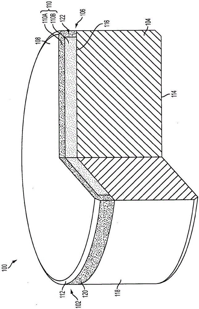
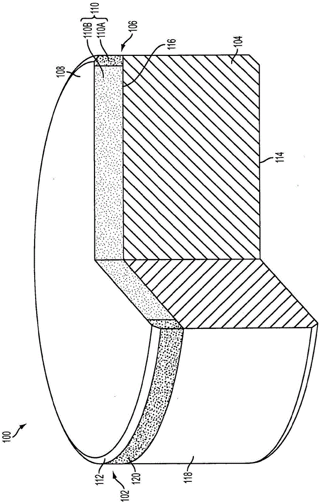
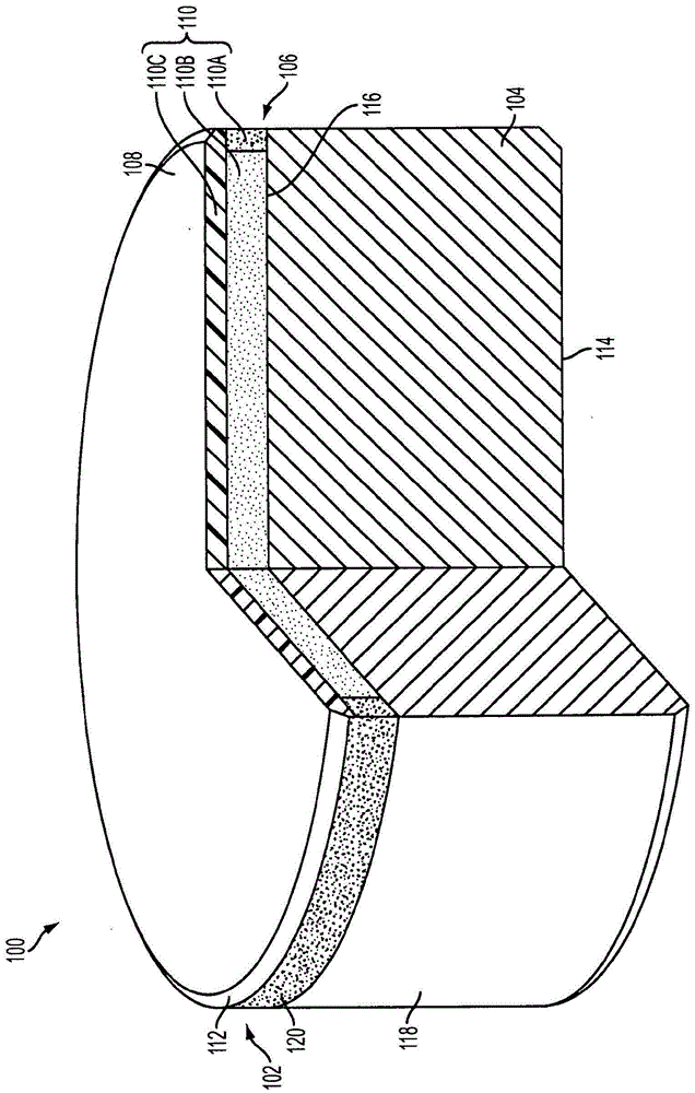
[0019] Cutting elements for drilling tools are described, methods for forming the cutting elements and drilling tools are also described. In some embodiments, the cutting element includes a polycrystalline compact attached to an end of a support matrix. The polycrystalline compact includes a first region extending from the support matrix and laterally surrounding a second region. The first region of the polycrystalline compact is less permeable than the second region of the polycrystalline compact. During the leaching process, the structural size (i.e., shape) and permeability of the first region can facilitate improved leaching velocity uniformity and leaching depth uniformity (compared to many conventional polycrystalline compacts), thereby, compared to many Compared with traditional cutting elements and tools, there will be less damage to cutting elements and defects on cutting elements, which will reduce manufacturing waste and improve performance and reliability.

[002...


PUM


Abstract

A cutting element comprises a supporting substrate, and a polycrystalline compact attached to an end of the supporting substrate. The polycrystalline compact comprises a region adjacent the end of the supporting substrate, and another region at least substantially laterally circumscribing the region and having lesser permeability than the region. A method of forming a cutting element, and an earth-boring tool are also described.

Description

[0001] priority statement [0002] This application claims the benefit of the filing date of U.S. Provisional Application Serial No. 13 / 953,307, filed July 29, 2013, entitled: Cutting Elements, Related Methods for Forming Cutting Elements, and Related earth-boring tools. technical field [0003] Embodiments of the present disclosure relate to cutting elements, related methods for forming cutting elements, and related drilling tools. Background technique [0004] A drilling tool for forming a borehole in a subterranean formation may include a plurality of cutting elements secured to a body. For example, fixed-blade drilling rotary drill bits ("drag bits") include a plurality of cutting elements that are rigidly attached to the bit body of the drill bit. Similarly, a roller cone drilling rotary bit may include cones mounted on cone shafts extending from the legs of the bit body so that each cone can rotate about the cone shaft (the cones are mounted on the gear shaft). Mul...

Claims


Application Information

Patent Timeline
Patent Type & Authority Applications(China)
IPC IPC(8): E21B10/42E21B10/46B24D18/00
CPCB24D18/0009B24D99/005E21B10/567E21B10/46E21B10/56
Inventor D·E·斯科特D·L·内尔姆斯
Owner BAKER HUGHES HLDG LLC
Learn More