Turbocharger core oil extraction device

A turbocharger and oil pumping technology, which is applied to chemical instruments and methods, cleaning methods and utensils, cleaning methods using gas flow, etc., can solve problems such as inability to meet production needs, poor effect, and high cost, and achieve false positives. No permanent oil leakage problem, low oil mist noise, and convenient operation

Active Publication Date: 2018-08-10
HUNAN TYEN MACHINERY
View PDF6 Cites 0 Cited by
  • Summary
  • Abstract
  • Description
  • Claims
  • Application Information

AI Technical Summary

Problems solved by technology

[0003] At present, there is no dedicated turbocharger core oil pumping device, which requires manual cleaning to remove the oil remaining in the turbocharger core. The cleaning process is costly and ineffective, and cannot meet production needs.

Method used


Image

  • Turbocharger core oil extraction device
  • Turbocharger core oil extraction device
  • Turbocharger core oil extraction device

Examples


Embodiment Construction

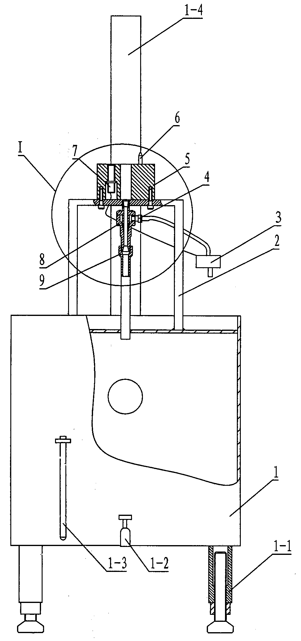
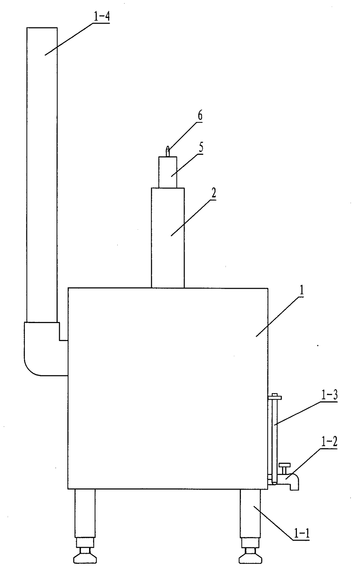
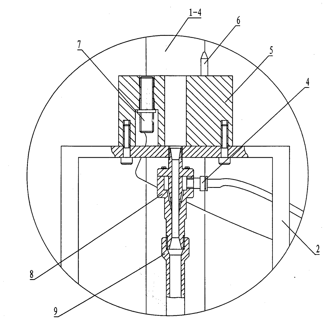
[0020] The turbocharger core oil pumping device includes a fuel tank 1, a bracket 2, a solenoid valve 3, an intake pipe joint 4, a connecting seat 5, a positioning pin 6, a proximity switch 7, an oil extractor 8 and an oil outlet pipe 9.

[0021] The front wall of the fuel tank 1 is respectively provided with an oil discharge tap 1-2, an oil mark 1-3, and an exhaust pipe 1-4 is arranged on the rear wall, and the exhaust pipe 1-4 communicates with the inner cavity of the fuel tank 1. The bottom of 1 is provided with adjustable foot support 1-1.

[0022] The connecting seat 5 is respectively provided with an oil outlet hole 5-1, a step hole 5-2 for installing the proximity switch 7, a threaded hole 5-5 for installing the positioning pin 6 and a threaded hole 5-4 connected with the bracket 2 , The small hole end of the step hole 5-2 is provided with an internal thread 5-3.

[0023] The oil extractor 8 includes a lower end body 8-2 and an upper end cover 8-1, the lower end body 8...


PUM


Abstract

The invention discloses a turbocharger core oil extracting device. The turbocharger core oil extracting device comprises an oil tank, a support, an electromagnetic valve, a gas inlet pipe connector, a connecting base, a positioning pin, a proximity switch, an oil extractor and an oil outlet pipe. The support is welded to a top plate of the oil tank. The connecting base is installed on a top plate of the support through screws. The proximity switch is fixed in a stepped hole of the connecting base through threaded connection. The positioning pin is installed in a threaded hole of the connecting base through threaded connection. One end of the oil extractor is installed at the bottom of the top plate of the support through threaded connection. An oil gas hole of the oil extractor communicates with an oil outlet of the connecting base. One end of the oil outlet pipe is installed on the other end of the oil extractor through threaded connection, and the other end of the oil outlet pipe extends into an inner cavity of the oil tank. The gas inlet pipe connector is installed in a threaded hole of the hole wall of a gas inlet cavity. The electromagnetic valve is connected with the gas inlet pipe connector through a gas pipe. The proximity switch is connected with the electromagnetic valve through a signal wire.

Description

technical field [0001] The invention relates to the technical field of engine turbochargers, in particular to a device for sucking oil from the core after the overall dynamic balance of the turbocharger. Background technique [0002] The dynamic balance of the whole turbine is a key process in the production of turbochargers. After the dynamic balance of the whole turbine, there will be a lot of oil remaining in the core of the turbocharger, which must be removed. It will cause false oil leakage when installing the machine. Therefore, the oil remaining in the core of the turbocharger must be removed before the main engine is installed. [0003] At present, there is no dedicated turbocharger core oil pumping device, which needs to be manually cleaned to remove the oil remaining in the turbocharger core. The cleaning process is costly and ineffective, and cannot meet the needs of production. Contents of the invention [0004] The object of the present invention is to overc...

Claims


Application Information

Patent Timeline
Patent Type & Authority Patents(China)
IPC IPC(8): B08B5/02
CPCB08B5/02
Inventor 袁普黄琼朱茂蒙胡辽平张爱明
Owner HUNAN TYEN MACHINERY
Why Eureka
Try Eureka