Stabilization method for optical device and components thereof

A technology of optical device and stabilization method, which is applied in the direction of optical components, optics, installation, etc., and can solve problems such as instability, unstable optical characteristics of the lens, and uncertain presentation position

Inactive Publication Date: 2018-06-26
SINTAI OPTICAL SHENZHEN CO LTD +1
View PDF7 Cites 0 Cited by
  • Summary
  • Abstract
  • Description
  • Claims
  • Application Information

AI Technical Summary

Problems solved by technology

[0004] see Figure 2-4 , in the above-mentioned known structure, because the first positioning surface 24 and the second positioning surface 34 are all planes, the contact position of the two planes will cause the first positioning surface 24 and the second positioning surface 24 to match the tolerance of the assembly due to the actual machining shape and the assembly tolerance. The contact point of the locating surface 34 may be at the upper end (as figure 2 shown), at the lower end (such as image 3 shown) or the rendering location is indeterminate (such as Figure 4 As shown), the returned position of the inner frame body 20 corresponds to the processing conditions of the components, resulting in an unstable phenomenon, and thus the optical characteristics of the produced lenses are unstable.

Method used


Image

  • Stabilization method for optical device and components thereof
  • Stabilization method for optical device and components thereof
  • Stabilization method for optical device and components thereof

Examples


Embodiment Construction

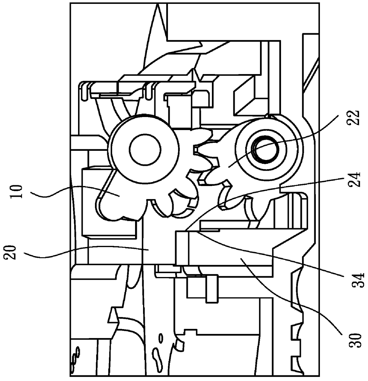
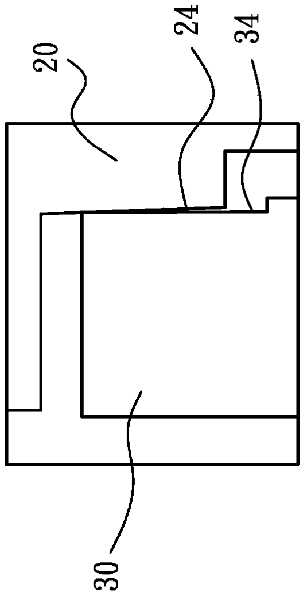
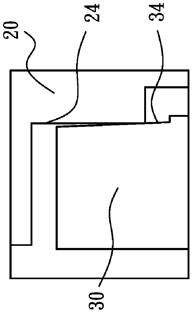
[0021] see Figure 5 , the optical device of the present invention is described by taking an optical lens as an example. The optical lens of the present invention includes a base (not shown), an image sensing component (not shown), an inner frame 120 , an outer frame 130 and a lens group (not shown). The image sensing component can be a charge-coupled device (CCD), which is arranged on the base, the outer frame body 130 is installed on the base, and the inner frame body 120 is rotatably arranged on the outer frame body 130, and the inner frame body 120 has The protrusion 122 , the outer frame body 130 has a plane 132 , the inner frame body 120 can move between a working position (first position) and a retracted position (second position), and the lens group is disposed on the inner frame body 120 . When the photographic device is activated, the optical lens is extended, and the inner frame body 120 is driven by the rotating claw (not shown) to rotate and move from the retract...


PUM


Abstract

The invention provides an optical device, which includes: a base, an image sensing unit, an outer frame, an inner frame, and a lens group. The image sensing unit is arranged on the base, the outer frame is connected to the base and has a plane, the inner frame has a protrusion, and can move between a first position and a second position relative to the base, and the lens group It is arranged on the inner frame body and has an optical axis. When the inner frame moves to the first position, the protrusion abuts against the plane and the optical axis of the lens group passes through the image sensing unit; when the inner frame moves to the second position, the inner The housing is accommodated in the retreat space. The invention also provides a method for stabilizing components of the optical device.

Description

technical field [0001] The present invention relates to a stabilizing method for an optical device and its components, in particular to a stabilizing method for an optical device and its components which increase the stability of the support between the components with a protruding structure. Background technique [0002] For existing photographic devices, when the camera is turned on and used, the lens of the camera will extend out of the body to receive a small amount of external light. Such a reversible lens group is usually designed to be able to move between the working position and the retracted position and to stably form an image on the image sensor component. When the camera is turned off, each lens group of the lens will overlap with each other and the lens will be retracted into the machine. in the body. As cameras become thinner and thinner, the overall structure requirements are becoming more and more delicate, so the lens groups of the lens are designed to be ...

Claims


Application Information

Patent Timeline
Patent Type & Authority Patents(China)
IPC IPC(8): G02B7/02G03B17/04
Inventor 陈宗礼黄胜杰
Owner SINTAI OPTICAL SHENZHEN CO LTD
Why Eureka
Try Eureka