Heat exchanger and air conditioner

A technology for heat exchangers and heat exchange parts, applied in heat exchange equipment, indirect heat exchangers, heat exchanger types, etc., can solve problems such as bias flow, and achieve the effect of suppressing bias flow

Active Publication Date: 2016-05-18
DAIKIN IND LTD
View PDF8 Cites 8 Cited by
  • Summary
  • Abstract
  • Description
  • Claims
  • Application Information

AI Technical Summary

Problems solved by technology

[0004] In the heat exchanger described in this patent document 1, there is the following technical problem: in the inside of the header tubes extending in the vertical direction,...

Method used


Image

  • Heat exchanger and air conditioner
  • Heat exchanger and air conditioner
  • Heat exchanger and air conditioner

Examples


Embodiment Construction

[0055] (1) Overall structure of the air conditioner 1

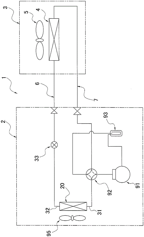
[0056] figure 1 It is a circuit diagram showing the outline of the configuration of the air conditioner 1 according to one embodiment of the present invention.

[0057] The air conditioner 1 is a device used for cooling and heating in a building in which an air conditioner indoor unit 3 is installed by performing a vapor compression refrigeration cycle operation. The indoor units 3 are connected by refrigerant communication pipes 6 and 7 .

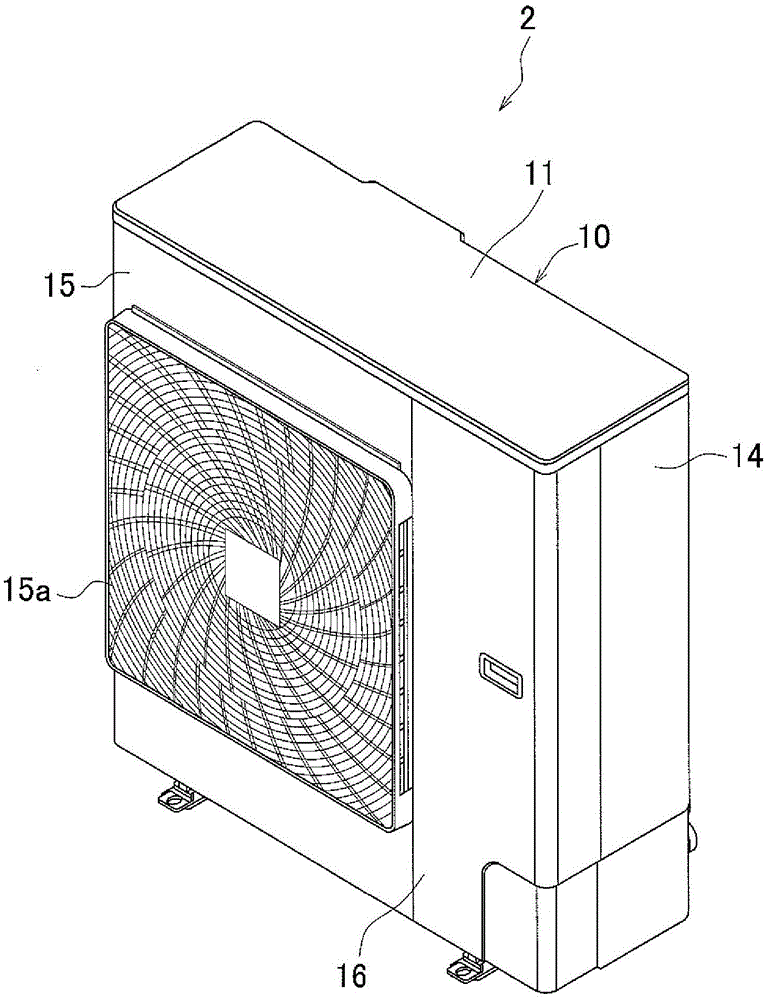
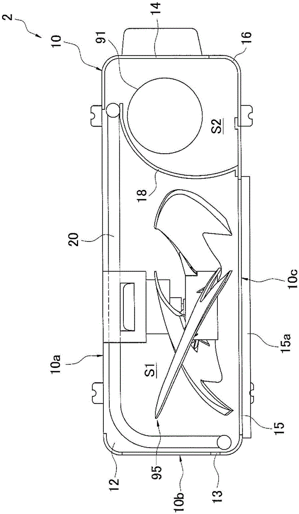
[0058] The refrigerant circuit formed by connecting the air-conditioning outdoor unit 2, the air-conditioning indoor unit 3, and the refrigerant communication pipes 6 and 7 is to connect the compressor 91, the four-way switching valve 92, the outdoor heat exchanger 20, and the expansion valve through refrigerant piping. 33. The indoor heat exchanger 4 and the storage tank 93 are connected to form. A refrigerant is sealed in this refrigerant circuit, and a refrigeration cycle operat...


PUM


Abstract

Provided are a heat exchanger and an air conditioner capable of inhibiting uneven flow of refrigerant even when used under conditions when the circulation flow changes. A plurality of flat perforated pipes (21b) are connected at different heights to a first inner space (23a) of a return header collecting pipe (23) of an outdoor heat exchanger (20). The first inner space (23a) uses a loop structure that includes a first partitioning plate (51), a first inlet (41x), a first upper communicating route (51x), and a first lower communicating route (51y). The first partitioning plate (51) partitions the first inner space (23a) into a first outflow space (51a) and a first loop space (51b). The first inlet (41x) is provided at the bottom of the first outflow space (51a) so that the refrigerant rises in the first outflow space (51a). Refrigerant that reaches the upper end of the first outflow space (51a) is guided to the first loop space (51b) via the first upper communicating route (51x), and the refrigerant that drops from the first loop space (51b) is returned to the first outflow space (51a) in a non-vertical direction via the first lower communicating route (51y).

Description

technical field [0001] The invention relates to a heat exchanger and an air conditioner. Background technique [0002] Conventionally, there is known a heat exchanger which has a plurality of flat tubes, fins joined to the plurality of flat tubes, header headers respectively connected to one end side and the other end side of the plurality of flat tubes, And the heat exchanger exchanges heat between the refrigerant flowing inside the flat tubes and the air flowing outside the flat tubes. [0003] For example, in the heat exchanger described in Patent Document 1 (Japanese Patent Application Laid-Open No. 2-219966), the following structure is adopted: both ends of a plurality of outflow pipes extending in the horizontal direction are respectively connected to collectors extending in the vertical direction. Tube manifold. [0004] In the heat exchanger described in this patent document 1, there is the following technical problem: in the inside of the header tubes extending in...

Claims


Application Information

Patent Timeline
IPC IPC(8): F28F9/02F25B41/00F28F9/22
CPCF25B13/00F25B39/00F28D1/0471F28D1/05391F28F1/30F28F1/325F28F9/027F28F9/028F25B39/028F28F9/0202F28F9/0275
Inventor 井上智嗣藤野宏和神藤正憲森本康介
Owner DAIKIN IND LTD
Why Eureka
Try Eureka