

Anchor rod impact test device and method thereof
A technology of impact test and anchor rod, which is applied in the field of material mechanical performance test and anchor rod impact test device, which can solve the problems such as the adjustable range of the weight of the drop hammer and the limited lifting height, high height, and difficulty in disassembly.
Active Publication Date: 2016-05-25
LIAONING TECHNICAL UNIVERSITY
View PDF7 Cites 5 Cited by
- Summary
- Abstract
- Description
- Claims
- Application Information
AI Technical Summary
Problems solved by technology
[0003] One of the existing test equipment is to carry out static tensile test on the anchor rod by means of static tension. However, this static test method lacks a special impact test device in line with the actual damage of the anchor rod, and the collected data is inaccurate.
The other is to use the dynamic test method. This method is to use the free fall of the drop hammer or the free swing of the pendulum to impact the anchor rod, and measure the force and deformation of the anchor rod during the process. The weight and height of the drop hammer are changed to provide The way of impact energy impacting the bolt requires a high height of the test equipment, and it is difficult to disassemble when increasing or decreasing the weight of the
Method used
View moreImage
Smart ImageViewing Examples

Examples
 PUM
 Abstract
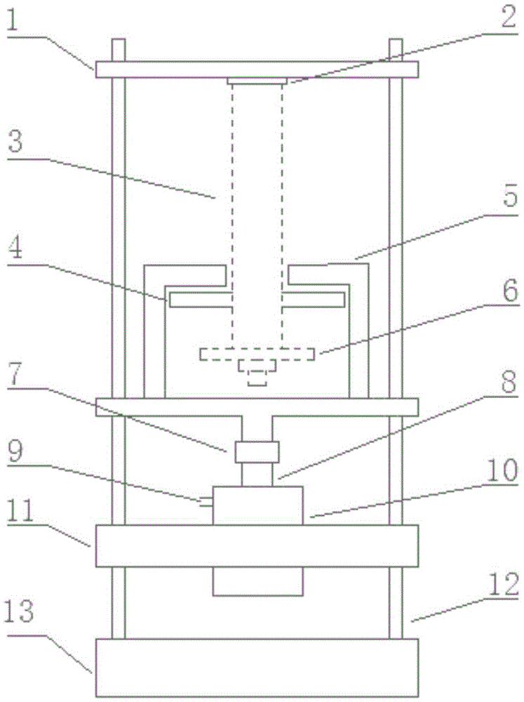
The invention discloses an anchor rod impact test device and a method thereof. The anchor rod impact test device and the method thereof are used for testing the mechanical properties of an anchor rod. The anchor rod impact test device comprises a base. Stand columns are fixed to the base, a top beam is arranged at the top ends of the stand columns, the anchor rod is fixed to the top beam, an impact beam is installed on the stand columns, a sensor is arranged on the impact beam, an impact plate is arranged on the anchor rod, and the impact beam is located above the impact plate. The impact beam impacts the impact plate under the action of an impact force application unit so as to stretch the anchor rod, and the sensor measures the mechanical parameters, generated in the stretching process, of the anchor rod. The impact force application unit can provide enough impact loads to impact the anchor rod so as to break the anchor rod, the maximum load value, generated in breaking, of the anchor rod and other mechanical parameters of the anchor rod can be conveniently measured, the measured values better meet impact force borne by the anchor rod when the anchor rod is damaged in practical use, and test results have higher accuracy and scientificity.
Description
technical field [0001] The invention belongs to the testing of mechanical properties of materials, relates to the technical field of mine support, in particular to a bolt impact test device. Background technique [0002] At present, due to the advantages of low support cost, fast roadway forming speed, and low labor intensity, bolt support has become a main support form of mine roadways in all countries in the world, and is widely used in coal mine roadways in my country. In actual mining activities, when rock burst occurs, the surrounding rock of the roadway is destroyed instantaneously, releasing a large amount of energy and causing axial impact on the anchor rod, which causes the anchor rod body to undergo tensile deformation. Therefore, in order to ensure the safe and efficient production of mines, it is very necessary to conduct special mechanical performance tests on bolts, especially those under dynamic loads. [0003] One of the existing test equipment is to carry o...
Claims
Login to View More Application Information
Patent Timeline
 IPC IPC(8): G01N3/307
CPCG01N3/307
Inventor潘一山朱小景唐治李忠华李国臻
OwnerLIAONING TECHNICAL UNIVERSITY