
Manufacturing method of invisible orthodontic tooth socket and invisible orthodontic tooth socket

A manufacturing method and invisible orthodontic technology, which is applied in orthodontics, dentistry, dental prosthetics, etc., can solve the problems of high price, difficult cleaning, and easy scratching of the oral cavity of invisible aligners

Inactive Publication Date: 2016-06-08
柯一石
View PDF9 Cites 6 Cited by
  • Summary
  • Abstract
  • Description
  • Claims
  • Application Information

AI Technical Summary

Problems solved by technology

[0003] For the user, although the orthodontic appliance has a good correction effect, it is not beautiful, difficult to clean, and easy to scratch the user's oral cavity
[0004] For the user, although the invisible aligner is beautiful, easy to clean and not easy to scratch the user's mouth, but because the invisible aligner drives the teeth to move through its rigid structure to correct the teeth, so in the initial stage of correction, If the user's teeth are not easy to move, the rigid structure of the invisible aligner will not provide enough force to correct the teeth, resulting in the inability to correct the teeth; in addition, if the user's teeth are too messy, the invisible aligner may not be fixed problems; again, when the user has missing teeth or dentures, etc., there is a possibility that the invisible aligner cannot be used; thirdly, the price of the invisible aligner is higher than the price of the dentition aligner; again , since the invisible aligner corrects the upper teeth and the lower teeth of the user separately, after the orthodontic treatment is completed and the invisible aligner is removed, it often happens that the upper teeth cannot occlude with the lower teeth

Method used


Image

  • Manufacturing method of invisible orthodontic tooth socket and invisible orthodontic tooth socket
  • Manufacturing method of invisible orthodontic tooth socket and invisible orthodontic tooth socket
  • Manufacturing method of invisible orthodontic tooth socket and invisible orthodontic tooth socket

Examples


Embodiment Construction

[0029] In order to fully understand the purpose, features and effects of the present invention, now through the following specific embodiments, and in conjunction with the accompanying drawings, the present invention is described in detail, as follows:

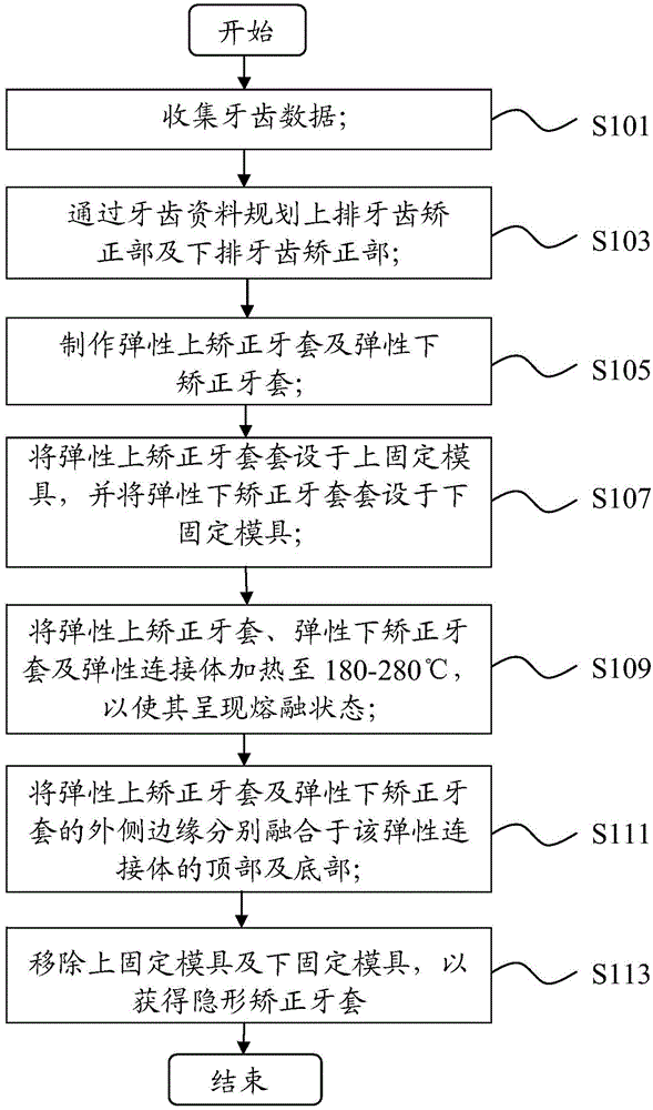
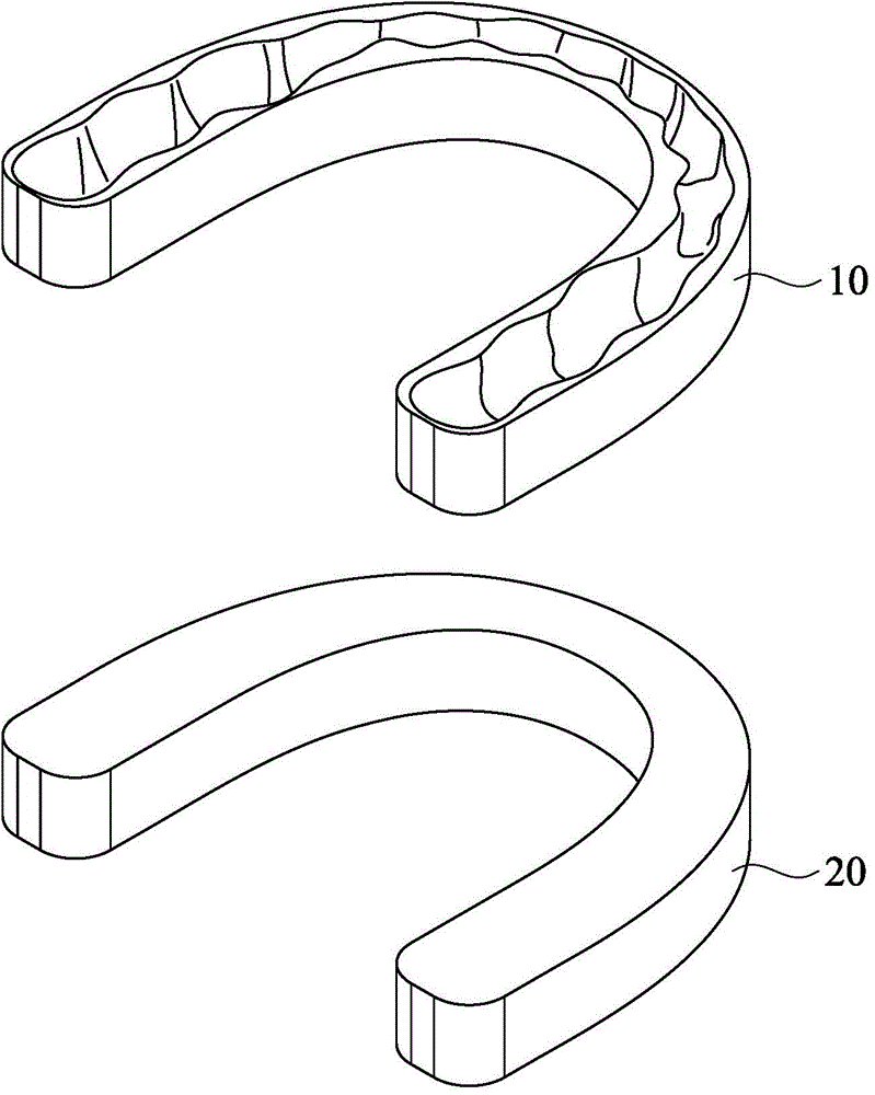
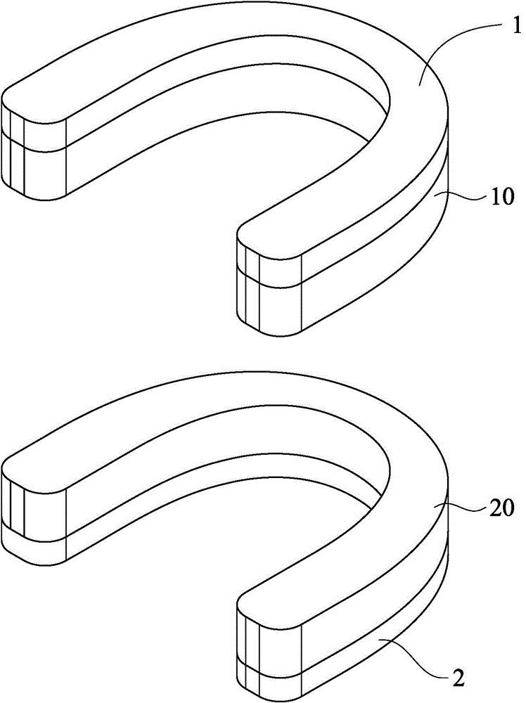
[0030] refer to figure 1 , is a flowchart of the manufacturing method of the invisible orthodontic braces of the present invention, and the manufacturing method includes seven steps. Below, will be figure 1 , Figure 2a to Figure 2e With a text description to illustrate the production method.

[0031] First, if figure 1 As shown, in step S101, the dental data of the user is collected, for example, the user's oral photos, scan files, bite records, etc. are usually collected.

[0032] Next, if figure 1 As shown, in step S103, plan the upper row of orthodontics and the lower row of orthodontics according to the dental data; more specifically, use the computer to analyze the dental data, and plan the user’s upper teeth and lo...


PUM


Abstract

The invention discloses a manufacturing method of an invisible orthodontic tooth socket; the manufacturing method comprises the following steps: collecting data of user teeth; planning an upper-row tooth orthodontic part and a lower-row tooth orthodontic part according to tooth information; making the upper-row tooth orthodontic part and the lower-row tooth orthodontic part into an elastic upper orthodontic tooth socket and an elastic lower orthodontic tooth socket; sleeving an upper fixed mold with the elastic upper orthodontic tooth socket, and sleeving a lower fixed mold with the elastic lower orthodontic tooth socket; heating the elastic upper orthodontic tooth socket, the elastic lower orthodontic tooth socket and an elastic connecting body to 180-280 DEG C; respectively fusing the elastic upper orthodontic tooth socket and the elastic lower orthodontic tooth socket to the top and the bottom of the elastic connecting body; and removing the upper fixed mold and the lower fixed mold to obtain the invisible orthodontic tooth socket. Therefore, the invisible orthodontic tooth socket is prepared, to provide enough power for correcting user teeth.

Description

technical field [0001] The invention relates to a manufacturing method of a dental aligner, in particular to a manufacturing method of an invisible orthodontic brace. The manufactured invisible orthodontic brace can provide sufficient strength to correct a user's upper teeth and lower teeth. Background technique [0002] Known orthodontic appliance has two kinds, and a kind of is dentition appliance, and another kind is invisible appliance. Both kinds of orthodontic appliances correct the teeth through gradual adjustment, but each has its own advantages and disadvantages. [0003] For the user, although the orthodontic device has a good correction effect, it is unsightly, difficult to clean, and easily scratches the user's oral cavity. [0004] For the user, although the invisible aligner is beautiful, easy to clean and not easy to scratch the user's mouth, but because the invisible aligner drives the teeth to move through its rigid structure to correct the teeth, so in the...

Claims


Application Information

Patent Timeline
Patent Type & Authority Applications(China)
IPC IPC(8): A61C7/00
Inventor 柯一石
Owner 柯一石
Learn More