Large steel plate splicing method and device

A splicing device, steel plate technology, applied in welding equipment, laser welding equipment, metal processing equipment and other directions, can solve the problems of many welding defects, many processes, large welding deformation and so on

Active Publication Date: 2017-12-15
GUANGDONG XINHUI CIMC SPECIAL TRANSPORT EQUIPS
View PDF7 Cites 0 Cited by
  • Summary
  • Abstract
  • Description
  • Claims
  • Application Information

AI Technical Summary

Problems solved by technology

[0003] The existing manufacturing method is to divide the whole container slab into several small parts, then process these small parts into several small semi-finished products, and then combine these small semi-finished products, And weld the joint between each small semi-finished product combination to make it an integral part, which has the following problems: 1, because it is divided into several small parts for manufacturing, there are many processes, the manufacturing cycle is lengthened, and the efficiency is low; 2. There are errors in the manufacturing process of each small part. When the overall assembly is carried out, the cumulative error is relatively large, which has a negative impact on the final assembly; 3. After assembling the small semi-finished products, the joint parts must be welded. Since there are many parts to be welded and the length of the weld seam is long, the welding deformation is large and there are many welding defects; 4. When welding the joint part, the pre-sprayed primer layer near the surface of the joint part will be destroyed, and at the same time There is hard skin on the surface of the weld, which needs to be shot blasted and painted again; 5. Due to the division into several small parts for processing, there are many processes, many workbenches, a large floor area, and a large number of workers at the same time

Method used


Image

  • Large steel plate splicing method and device
  • Large steel plate splicing method and device
  • Large steel plate splicing method and device

Examples


Embodiment Construction

[0039] The present invention will be further elaborated below in conjunction with the accompanying drawings.

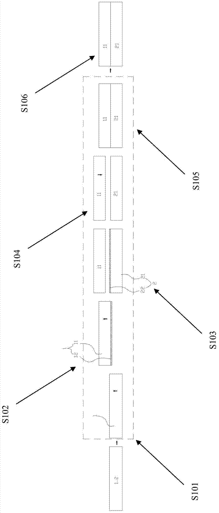
[0040] see figure 1 , figure 1 It is a schematic flow chart of the first embodiment of the large-scale steel plate splicing method of the present invention. It roughly includes the following steps:

[0041] S101, sending the first steel plate 1 vertically and horizontally to the first station;

[0042] S102. Horizontally move the first steel plate 1 from the first station to the cutting position on the side to be spliced ​​and be clamped, perform laser cutting along the straight line X, remove the cutting edge 12, and then make the cut The main body 11 of the first steel plate 1 is laterally displaced outward by a set distance to the second station, and kept clamped;

[0043] S103. Send the second steel plate 2 vertically and horizontally to the first station and clamp it, and perform laser cutting along the straight line X, remove the cutting edge 22, and the mai...


PUM

PropertyMeasurementUnit
sizeaaaaaaaaaa
lengthaaaaaaaaaa
widthaaaaaaaaaa

Abstract

The invention provides a method and device for splicing large-width steel plates. The method comprises the following steps that the to-be-spliced side of the first steel plate is located at a cutting position and clamped, laser cutting treatment is firstly carried out along a linear track, and then the first steel plate is transversely moved outwards by a set distance; the to-be-spliced side of the second steel plate is located at the cutting position and clamped, and laser cutting treatment is carried out along the linear track; and the first steel plate is transversely moved inwards, so that the two spliced sides are attached till the clearance requirement of welding is met, and then laser welding treatment or laser hybrid welding treatment is carried out along the linear track, so that the two to-be-spliced single steel plates are spliced. According to the method and device, the width size of the steel plates can break through the limitation of the width size of existing steel plate coils efficiently.

Description

technical field [0001] The invention relates to the splicing technology of large steel plates, in particular to the splicing technology capable of realizing the width dimension of the steel plates breaking through the limitation of the width dimension of the existing steel plate coils. Background technique [0002] Limited by the maximum width of the existing steel coil, the manufacturing process of the roof of the existing container roughly includes: opening the steel coil to make a single flat unit; The finished roof unit is made into a container roof. Similarly, the container side panel also includes the process of making a single flat panel unit from a steel coil; making a single side panel unit finished product from a single flat panel unit and making a container side panel from more than five single side panel unit products. The container front wall panel also includes the process of making a single flat panel unit from a steel coil; making a single front wall panel u...

Claims


Application Information

Patent Timeline
Patent Type & Authority Patents(China)
IPC IPC(8): B23K26/38B23K26/21B23K26/70
CPCB23K26/20B23K26/38
Inventor 姚谷李柘林
Owner GUANGDONG XINHUI CIMC SPECIAL TRANSPORT EQUIPS
Why Eureka
Try Eureka