Position-adjustable pad printing jig

An adjustable pad printing technology, applied in printing, printing machines, rotary printing machines, etc., can solve the problem that pad printing speed is difficult to increase, and achieve the effect of improving efficiency

Inactive Publication Date: 2016-06-08
赵齐赞
View PDF5 Cites 0 Cited by
  • Summary
  • Abstract
  • Description
  • Claims
  • Application Information

AI Technical Summary

Problems solved by technology

[0002] It is difficult to print multiple fixed pad printing products on continuous products with traditional pad printing fixtures. Traditional pad printing fixtures require one piece of material to be picked and placed once, and due to personnel taking and placing Due to the limitation of material speed, pad printing speed is also difficult to improve

Method used


Image

  • Position-adjustable pad printing jig
  • Position-adjustable pad printing jig
  • Position-adjustable pad printing jig

Examples


Embodiment Construction

[0016] The following will clearly and completely describe the technical solutions in the embodiments of the present invention with reference to the accompanying drawings in the embodiments of the present invention. Obviously, the described embodiments are only some, not all, embodiments of the present invention. Based on the embodiments of the present invention, all other embodiments obtained by persons of ordinary skill in the art without making creative efforts belong to the protection scope of the present invention.

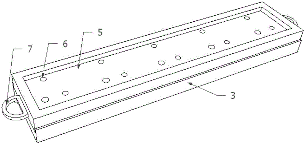
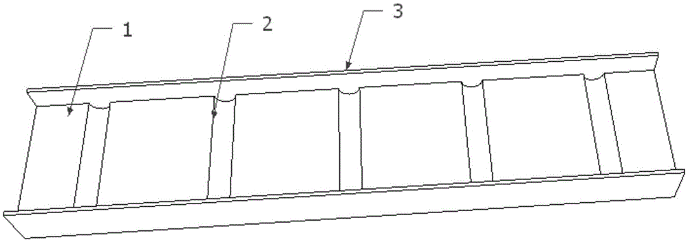
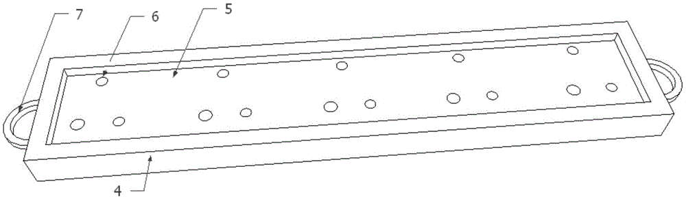
[0017] Such as figure 1 As shown, a position-adjustable pad printing fixture includes a base 1 and a sliding seat 4, the base 1 is fixed on the pad printing machine table, and the upper surface of the base 1 is longitudinally provided with multiple rows of arcs at a certain interval. shaped groove 2, the bottom surface of the sliding seat 4 is provided with an arc-shaped protrusion 8 corresponding to the arc-shaped groove, the upper part of the sliding seat 4 ...


PUM


Abstract

The invention belongs to the field of pad printing jigs, and particularly relates to a position-adjustable pad printing jig. The position-adjustable pad printing jig comprises a base and a sliding base. The base is fixed to a pad printing machine table. Multiple lines of arc-shaped grooves are formed in the upper surface of the base at certain intervals in the longitudinal direction. Arc-shaped protrusions corresponding to the arc-shaped grooves are arranged on the surface of the bottom of the sliding base. A long material groove is formed in the upper portion of the sliding base. Positioning holes matched with pad printing products are formed in the material groove. At least one longitudinal line of arc-shaped protrusions are arranged at the bottom of a bottom plate. Limiting blocks are arranged on the two sides of the base. A handle is arranged on the sliding base in the sliding direction. Multiple or a whole to-be-printed product can be put in the material groove, continuous printing is achieved by pulling the sliding base, and the operation efficiency of personnel can also be improved.

Description

technical field [0001] The invention belongs to the field of pad printing fixtures, in particular to a position-adjustable pad printing fixture. Background technique [0002] It is difficult to print multiple fixed pad printing products on continuous products with traditional pad printing fixtures. Traditional pad printing fixtures require one piece of material to be picked and placed once, and due to personnel taking and placing Due to the limitation of material speed, it is difficult to improve the pad printing speed. Contents of the invention [0003] The purpose of the present invention is to provide a position-adjustable pad printing fixture to solve the problems raised in the above-mentioned background technology. [0004] The technical problem to be solved by the present invention adopts the following technical solutions to realize: [0005] A position-adjustable pad printing fixture, including a base and a sliding seat, the base is fixed on the pad printing machi...

Claims


Application Information

Patent Timeline
Patent Type & Authority Applications(China)
IPC IPC(8): B41F17/00
CPCB41F17/00
Inventor 赵齐赞
Owner 赵齐赞
Why Eureka
Try Eureka