
Vehicle roof trunk
A luggage and box body technology, applied in the luggage field, can solve the problems of easy safety accidents, inconvenience and cumbersomeness, etc.
- Summary
- Abstract
- Description
- Claims
- Application Information
AI Technical Summary
Problems solved by technology
Method used
Image

Examples
Embodiment Construction
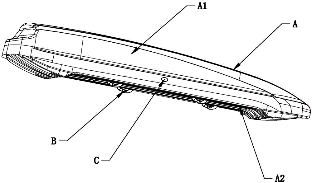
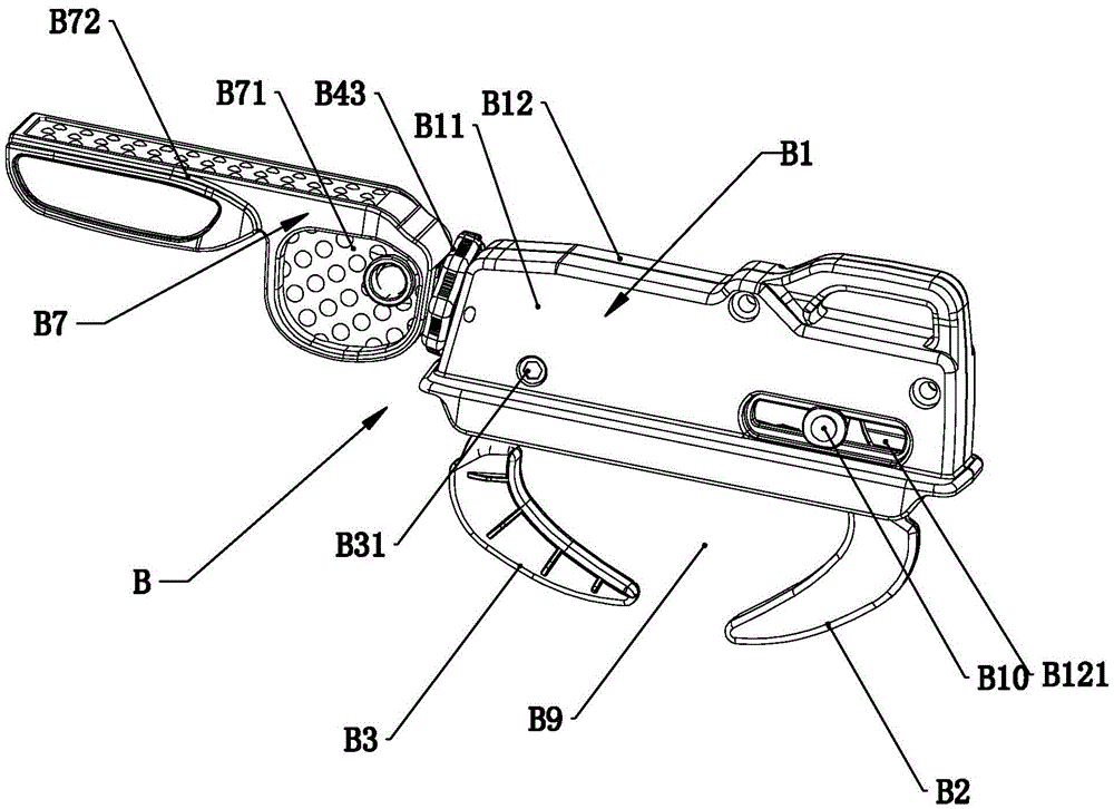
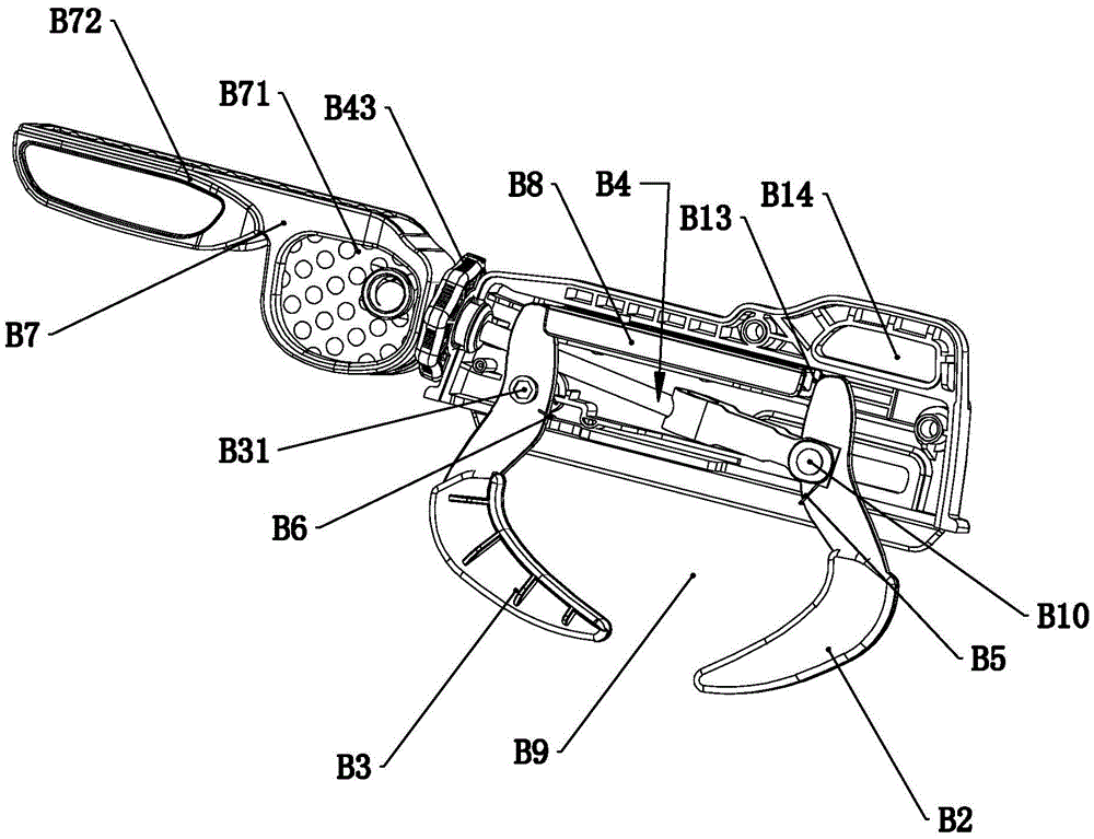
[0024] Such as figure 1 — Figure 15As shown, a roof box includes a box body A, a quick connector B arranged on the box body A, and a lock C for the roof box body. The box body A includes an upper box body A1 and a lower box body A2 , the lower box body A2 is provided with a through hole, the quick connector B is arranged at the position of the through hole, the lower ends of the first handle B2 and the second handle B3 of the quick connector B protrude from the through hole, The quick connector B includes a housing B1, a first handle B2, a second handle B3, a pull rod B4, a first torsion spring B5, a second torsion spring B6, an eccentric wheel handle B7 and a support rod B8. The upper ends of the first gripper B2 and the second gripper B3 are set inside the housing B1, the lower ends of the first gripper B2 and the second gripper B3 are located outside the housing B1 to form a clamping area B9, and one end of the pull rod B4 Hinged to the upper end of the first handle B2 t...
PUM
 Abstract
Description
Claims
Application Information