Composite material propeller cavitation performance calculation method

A composite material and calculation method technology, applied in the direction of calculation, design optimization/simulation, special data processing applications, etc., can solve problems such as affecting the hydrodynamic performance of the propeller, eroding the propeller, reducing the propulsion efficiency, etc.

Active Publication Date: 2016-06-08
HARBIN INST OF TECH
View PDF5 Cites 18 Cited by
  • Summary
  • Abstract
  • Description
  • Claims
  • Application Information

AI Technical Summary

Problems solved by technology

[0004] The present invention aims to solve the problem that the existing method will affect the hydrodynamic performance of the propeller due to the generation of cavitation, reduce the propulsion efficiency, seriously affect the concealment of the ship, erode the surface material of the propeller, cause surface material defects and affect the hydrodynamic performance of the propeller, and A Calculation Method for Composite Propeller Cavitation Performance is Proposed

Method used


Image

  • Composite material propeller cavitation performance calculation method
  • Composite material propeller cavitation performance calculation method
  • Composite material propeller cavitation performance calculation method

Examples


specific Embodiment approach 1

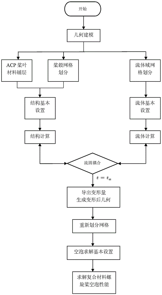
[0020] Specific embodiment one: the calculation method of a kind of composite material propeller cavitation performance of the present embodiment, it realizes according to the following steps:

[0021] Step 1. Use the three-dimensional modeling software CAD to establish the geometric model of the composite material propeller. The coordinate system where the propeller is located is the Cartesian coordinate system. The X axis is taken as the rotation axis of the propeller, and the positive X direction is the incoming flow direction;

[0022] Step 2. Establishing the composite material propeller fluid calculation domain in the meshing software and dividing the mesh;

[0023] Step 3. Fluid basic setting: use computational fluid dynamics software based on RANS equation to establish the solution equation for the hydrodynamic performance of the composite propeller, set the solution parameters, boundary conditions, start the dynamic mesh, and define the composite propeller blade part a...

specific Embodiment approach 2

[0032] Embodiment 2: The difference between this embodiment and Embodiment 1 is that in the step 2, the composite material propeller fluid calculation domain is divided into an outer domain and an inner domain, and the inner domain includes a composite material propeller as a rotating area, and an unstructured grid is used. Division; the outer domain is a static area, which is divided into structural grids; wherein, the composite material propeller fluid calculation domain includes the geometric model of the composite material propeller in step 1.

[0033] Other steps and parameters are the same as those in Embodiment 1.

specific Embodiment approach 3

[0034] Specific embodiment three: the difference between this embodiment and specific embodiment one or two is: the RANS equation in the step three is

[0035] ∂ ∂ t ( ρu i ) + ∂ ∂ x j ( ρu i u j ) = - ∂ p ∂ x i + ∂ ∂ x j ( μ ∂ u i ...


PUM


Abstract

A composite propeller cavitation performance calculation method. The present invention relates to a composite material propeller cavitation performance calculation method. In order to solve the problem that due to generation of cavitation, the existing method will affect hydrodynamic performance of propellers, reduce propulsion efficiency, severely affect concealment of vessels, corrode surface materials of the propellers and cause surface material defects, the present invention provides a composite material propeller cavitation performance calculation method. The method comprises: establishing a geometric model; carrying out grid division; carrying out structure and fluid arrangement; carrying out structure and fluid calculation; exporting a deformed geometric model; re-dividing a grid; and carrying out cavitation performance calculation. The method provided by the present invention is applied to the field of propellers.

Description

technical field [0001] The invention relates to a calculation method for the cavitation performance of a composite material propeller. Background technique [0002] The research work on composite material propellers started in the 1960s and has been developed up to now. Compared with traditional metal propellers, its light weight, high specific stiffness, high specific strength, and corrosion resistance are gradually being applied to the field of high-performance ships. The future will replace the traditional metal propeller. However, due to the deformation characteristics of composite materials, the difficulty of research work is greatly increased, and the influence of fluid and structure needs to be considered at the same time. With the continuous development of underwater detection equipment in the direction of accuracy and detection distance, more stringent requirements are put forward for the stealth performance and navigation environment of ships. The research work of...

Claims


Application Information

Patent Timeline
Patent Type & Authority Applications(China)
IPC IPC(8): G06F17/50
CPCG06F30/23G06F30/367Y02T90/00
Inventor 王荣国张旭婷洪毅赫晓东刘文博矫维成
Owner HARBIN INST OF TECH
Why Eureka
Try Eureka