Lashing bridge for a cargo ship

A technology for lashing bridges and cargo ships, which is applied in the directions of preventing multi-way movement of goods, ship accessories, ships, etc., can solve the problems of expensive, unfavorable transmission of force and load on the lashing bridge, and achieves cheap manufacturing and reduced vibration of the lashing bridge. Effect

Active Publication Date: 2016-06-08
MACGREGOR FINLAND
View PDF9 Cites 15 Cited by
  • Summary
  • Abstract
  • Description
  • Claims
  • Application Information

AI Technical Summary

Problems solved by technology

[0008] In earlier solutions, the geometry of the lashing bridge designed in this way caused the main forces and loads in the structure to be unfavorably transferred to the hull of the vessel
T

Method used


Image

  • Lashing bridge for a cargo ship
  • Lashing bridge for a cargo ship
  • Lashing bridge for a cargo ship

Examples


Embodiment Construction

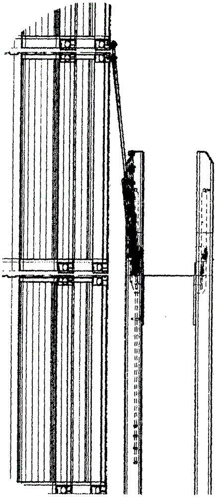
[0020] Accordingly, Figures 1-3 illustrate the prior art. These figures are shown to make it easier to understand the differences between the prior art and the present invention, which are not described in any more detail below. Figures 1 and 2 show the lashing bar (in this case with 2 units) between the lashing bridge and the stack of containers. The lack of verticality of the lashing bars seen in Figure 2 creates forces on the lashing bridge in the longitudinal direction of the ship.

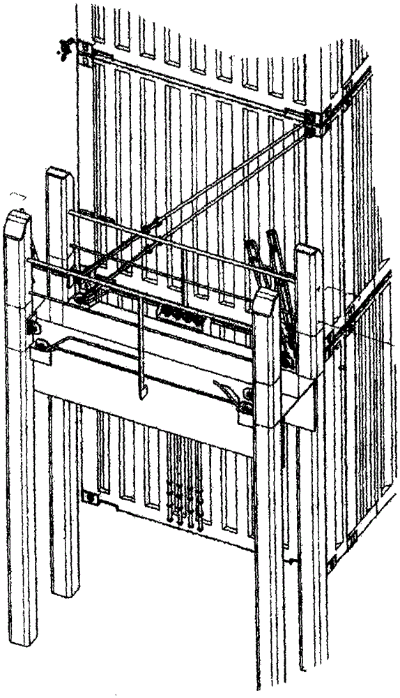
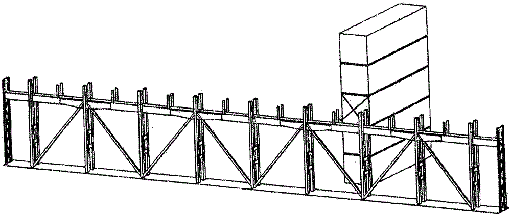
[0021] Figure 4 and Figure 5 The invention is shown. The lashing bridge 1 of a cargo ship is usually arranged along the transverse direction of the ship and the containers / container stacks 2 are arranged between them in such a way that the lashing bars 3 of the containers can be fixed between the containers 2 and the lashing bridge 1 . The lashing bridges 1 are of different heights, generally they extend from the level of the weather deck of the ship to the height of two, three or four co...


PUM


Abstract

A lashing bridge (1) for a cargo ship for supporting containers (2) during transport, which lashing bridge (1) is installed on the deck of the cargo ship in the transverse direction of the cargo ship, and which lashing bridge (1) comprises fixing points (5) for fixing lashing bars (3) to it, which lashing bars (3) are fixed at their other end to the containers (2). The invention is implemented in such a way that at least one tension bar (9) is fixed to the lashing bridge (1) for conveying essentially only the upward forces exerted on the lashing bridge (1) by the lashing bars (3) to the hull of the cargo ship.

Description

technical field [0001] The object of the present invention is a lashing bridge for a cargo ship for supporting containers during transport, said lashing bridge being mounted on the deck of the cargo ship in the transverse direction of the cargo ship and comprising a lashing bar for securing thereto A fixed point, the lashing rod is fixed at the other end to the container. [0002] The object of the invention is a supporting frame (so-called lashing bridge) to be installed on the deck of a cargo ship and intended for transporting containers. The lashing rods to be used to support the containers are fixed to the structure in question. Background technique [0003] On a cargo ship, containers are usually transported above and below deck in rows and columns and in multiple layers stacked on top of each other. Below the deck are rails on which the containers are supported when at sea. Removable hatches above the deck keep the cargo hold below closed by means of the hatch. The...

Claims


Application Information

Patent Timeline
IPC IPC(8): B63B25/28B63B25/00
CPCB63B25/28B63B2025/285B63B25/24B63B25/22
Inventor J·米科拉
Owner MACGREGOR FINLAND
Why Eureka
Try Eureka