hydrostatic axial piston machine

An axial piston machine, hydrostatic technology, applied in reciprocating piston engines, components of pumping devices for elastic fluids, liquid fuel engines, etc., can solve the problem of increasing weight and material consumption, hindering the preparation of casing vibration , can not provide the gap of the additional mass of acoustic measures, etc., to achieve the effect of light weight, reduce vibration tendency, and reduce weight

Inactive Publication Date: 2016-12-07
ROBERT BOSCH GMBH
View PDF7 Cites 0 Cited by
  • Summary
  • Abstract
  • Description
  • Claims
  • Application Information

AI Technical Summary

Problems solved by technology

Since the force flow is guided entirely through the housing, the housing must be dimensioned accordingly, which increases weight and material consumption
Since the lower weight limit for housings, in particular sand-cast housings, is already specified by the minimum wall thicknesses and surfaces of the manufacturing process and the requirements for a structurally space-saving design with the lowest possible weight tend to increase, therefore Gaps that provide little additional mass for acoustic measures
In addition, the known measures for reducing noise do not reduce the vibration excitation, but only hinder the vibration preparation of the housing

Method used


Image

  • hydrostatic axial piston machine
  • hydrostatic axial piston machine
  • hydrostatic axial piston machine

Examples


Embodiment Construction

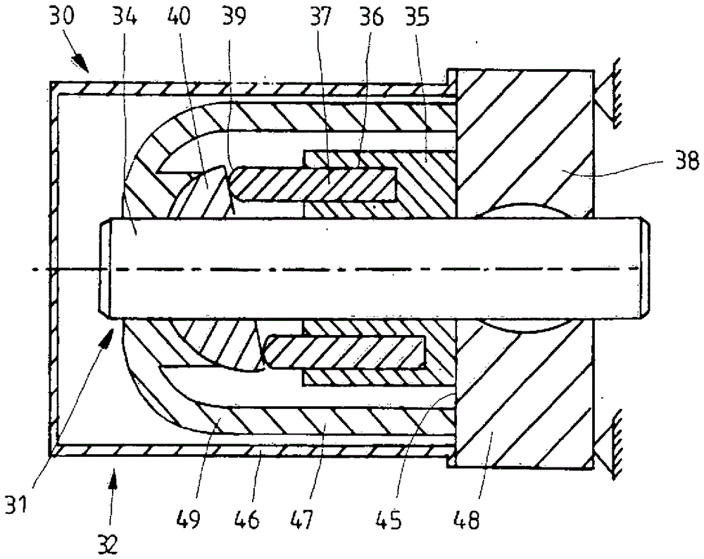
[0026] exist figure 1 The axial piston machine 1 shown in , which is designed as a swash plate, has a drive 2 which is arranged in a housing 3 . As main components, the drive mechanism 2 comprises a drive shaft 4 rotatably mounted via two roller bearings 8, 9, a cylinder drum 5, a housing-fixed connecting plate 10 coaxially passed through by the drive shaft 4, said cylinder drum having An axially extending cylinder bore 6 arranged on a partial circle with a longitudinally displaceable piston 7 in said cylinder bore is non-rotatably and axially displaceably connected to the drive via a synchronizing area 11 in the form of a cylinder tooth. Axis 4 is connected.

[0027] The piston 7 , which is guided longitudinally displaceably in the cylinder bore 6 , has a cylindrical configuration. The ends of the pistons 7 facing away from the cylinder drum are each supported on a swash plate 13 via hinges 12 .

[0028] The drive shaft 4 passes through the swash plate 13 . What is not sh...


PUM


Abstract

The invention relates to a hydrostatic machine (1), in particular an axial piston machine, with a housing (3, 32) comprising an inner housing part (47) for receiving a force flow, with It consists of an outer housing part (46) and a housing bottom (10, 38, 48) for sealing and damping, and also has a drive shaft (4, 34) which runs coaxially through the The housing bottom ( 10 , 38 , 48 ) and away from the drive side runs coaxially through the swash plate ( 13 , 40 ) and is non-rotatably connected to the cylinder drum ( 5 , 35 ). The object of the present invention is to realize a hydrostatic machine of the type mentioned at the outset, in particular an axial piston machine, which is constructed in a weight-saving manner and at the same time reduces the transmission of vibrations and the resulting noise generation. This task is achieved in that the drive shaft (4, 34) passes at least partially only through the inner housing part (47) and is mounted rotatably on the housing bottom (10, 38, 48) and the inner housing member (47).

Description

technical field [0001] The invention relates to a hydrostatic axial piston machine with a housing consisting of an inner housing part, an outer housing part and a housing bottom, and which also has a drive shaft, The drive shaft runs coaxially through the housing bottom on the drive side, is non-rotatably connected to the cylinder drum and passes through the swash plate on the drive side. Background technique [0002] Known axial piston machines of this design have a drive shaft mounted rotatably in a housing, which passes through the swash plate on the drive side, the cylinder drums being non-rotatably and axially displaceable via a synchronizing zone is connected to the swash plate and coaxially passes through the fixed connection plate of the housing. The cylinder drum has longitudinally displaceable extruders in cylinder bores arranged on the partial circle. The swash plate is supported inside the housing. During operation, internal dynamic forces are produced which a...

Claims


Application Information

Patent Timeline
Patent Type & Authority Patents(China)
IPC IPC(8): F04B39/00F04B39/12F04B53/00F04B1/20
CPCF01B3/0026F04B1/2064F04B39/0044F04B39/121F04B53/003F04B27/0612F04B1/20F04B1/2078F04B1/128
Inventor J.施密特P.克劳泽U.比特纳J.科佩基D.布罗伊尔
Owner ROBERT BOSCH GMBH
Why Eureka
Try Eureka