Machine to produce a fibrous web

a fibrous web and machine technology, applied in papermaking, non-fibrous pulp addition, press section, etc., can solve the problems of unintentionally influencing the line force in the creping nip, high load on the textured belt serving as the creping belt, etc., to reduce operating and investment costs, stable process, and good paper quality

Active Publication Date: 2011-05-31
GPCP IP HLDG LLC
View PDF32 Cites 0 Cited by
  • Summary
  • Abstract
  • Description
  • Claims
  • Application Information

AI Technical Summary

Benefits of technology

[0009]The present invention is designed such that the technology that includes the creping process by way of a textured belt may be integrated into a stable process and a good paper quality achieved, while reducing the operating and investment costs and increasing runability.
[0012]Alternatively, the press roller may also be in the embodiment of a shoe press roller or a suction press roller. According to a preferred practical design variation of the inventive machine, the press roller is also equipped with its own drive. Advantageously the textured belt is guided by guide rollers. In order to achieve an as uniform as possible tensile stress over the entire length of the textured belt it is advantageous if at least one of the guide rollers is equipped with its own drive.
[0015]In accordance with another practical embodiment of the present invention, the press unit is a shoe press unit, preferably a shoe press roll with a relatively flexible roll shell. The dryer cylinder, which receives the fibrous web from the textured belt, is a Yankee-cylinder. In one embodiment of the present invention, the backing roll is embodied by a dryer cylinder. A dryer hood may be allocated to the backing roll. It is also advantageous if the backing roll possesses a smooth surface or is respectively equipped with a smooth cover.
[0017]The present invention therefore eliminates the possibility that the effects of the speed differential between the creping roll and the backing roll act upon the pressure force with which the creping roll is pressed against the backing roll, for example, during vibrations in the rotational movement of the creping roll, or during the so-called “slip-stick” effects.
[0019]Amongst others, the following advantages are achieved with the apparatus of the present invention:
[0020]The wire tension prior to the creping roll is reduced since there is no longer a braking effect occurring prior to the creping roll. Since the drives of the creping roll and the backing roll are frictionally engaged with each other through the creping nip, the vibration tendency of the system is reduced to a minimum. In addition, the influence of the very high wire tension upon the line force between the creping roll and the backing roll is further largely eliminated, especially when a change in the speed differential occurs. The positioning of the pivoting lever, which is allocated to the creping roll, prevents an effect upon the line force caused by the frictional force which occurs in the creping nip. The vibration tendency of the system is reduced to a minimum. In addition, a longer lifespan is achieved for the textured belt or the TAD wire respectively.

Problems solved by technology

A problem with the machine of the type referred to therein is in the necessary speed differential between the creping roll and the backing roll.
This speed differential may vary with each different paper type, especially relative to the desired creping factor, resulting in a high load upon the textured belt serving as the creping belt.
This results in an additional problem due to frictional force, which could unintentionally influence the line force in the creping nip.

Method used


Image

  • Machine to produce a fibrous web
  • Machine to produce a fibrous web

Examples


Embodiment Construction

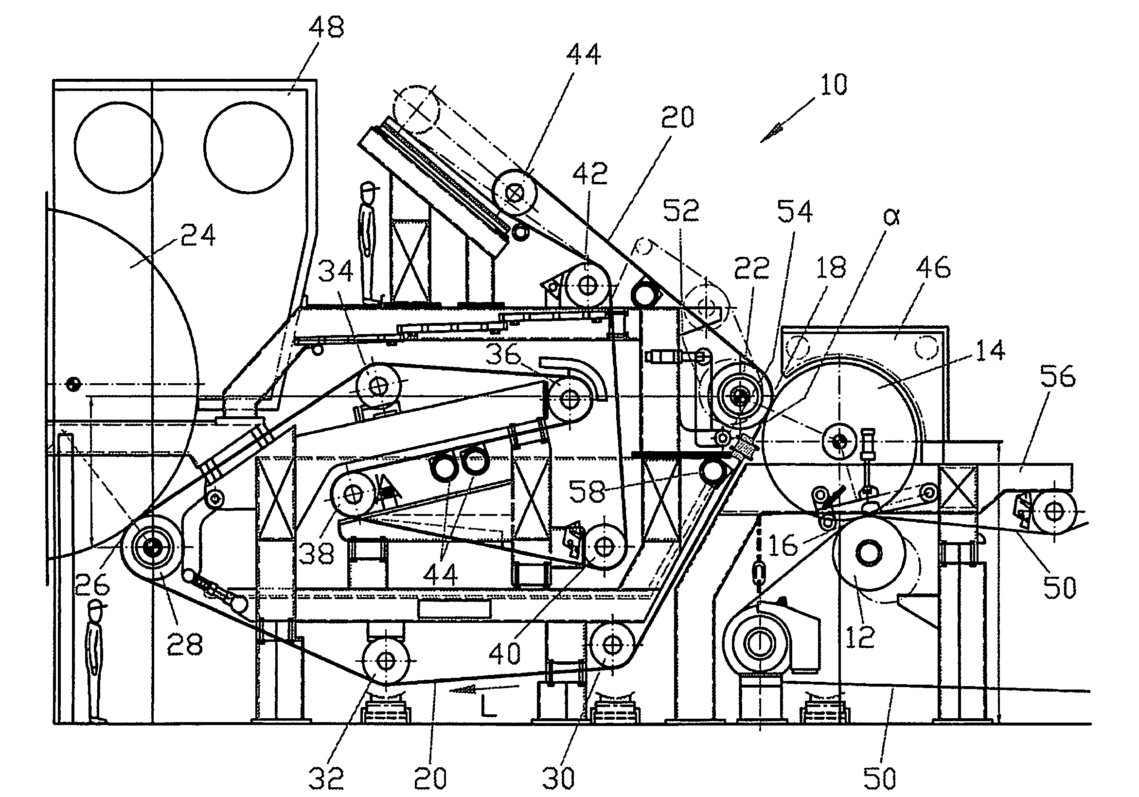
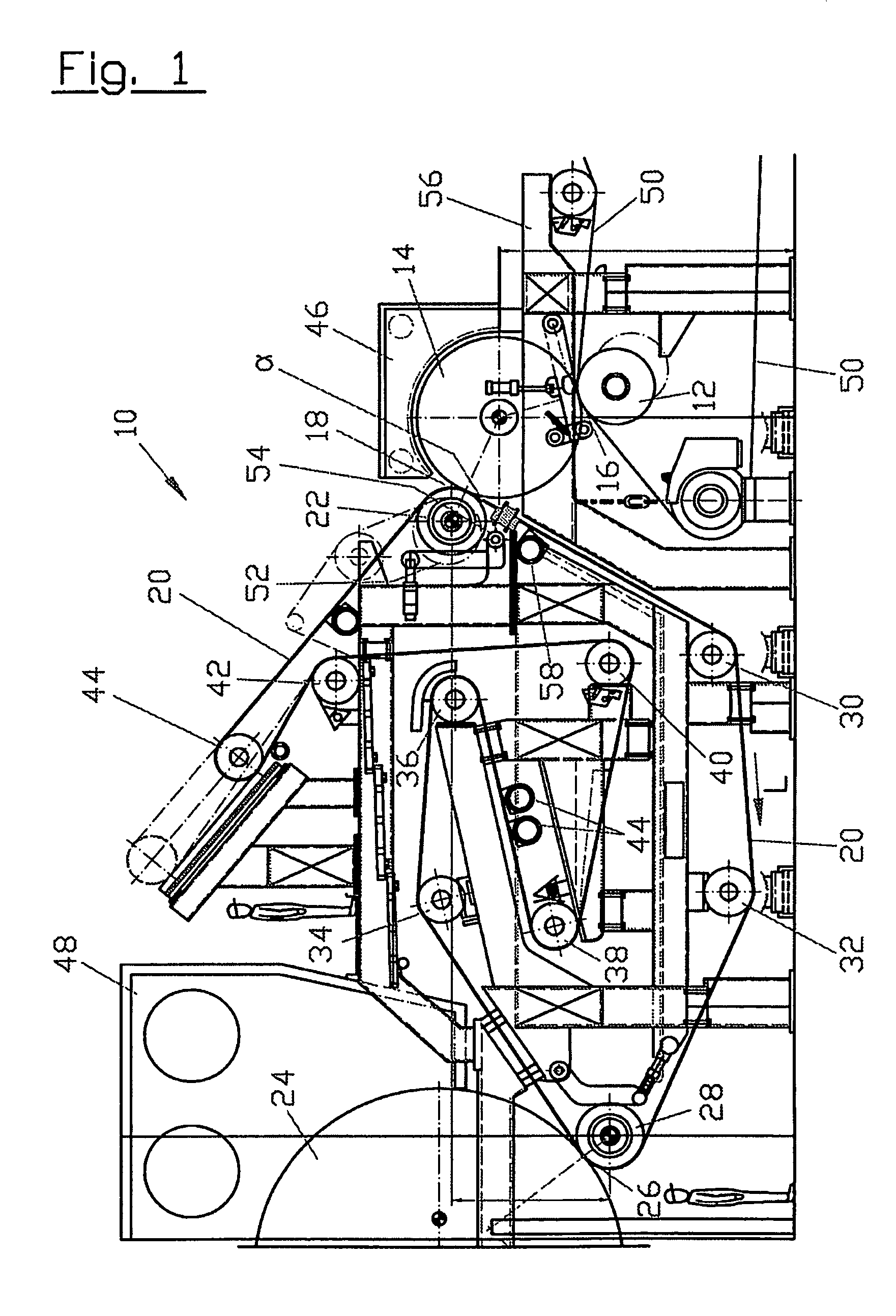
[0025]Referring now to the drawings, and more particularly to FIG. 1, there is shown an apparatus 10, also known as a papermaking machine 10, with a fibrous web running through a press nip 16, which is formed between a press unit 12 and a backing roll 14. The fibrous web then runs through a creping nip 18 which is formed between backing roll 14 and a creping roll 22 around which a textured belt 20 is looped. In this example, creping roll 22 is equipped with its own drive, which means that creping roll 22 is driven directly.

[0026]In one embodiment of the present invention backing roll 14 is also equipped with its own drive, in other words it is also driven directly, whereby for example, the driving power of creping roll 22 is lower than the driving power of backing roll 14.

[0027]After creping nip 18 the fibrous web, together with textured belt 20, which may be a structural belt 2 or a permeable structural belt 2 is carried to a dryer cylinder 24, onto which the fibrous web is transfe...


PUM

PropertyMeasurementUnit
angleaaaaaaaaaa
flexibleaaaaaaaaaa
speedaaaaaaaaaa

Abstract

An apparatus for the production of a fibrous web, especially a tissue or hygienic web, the fibrous web runs through a press nip which is formed by a press unit and a backing roll and the web is subsequently run through a creping nip which is formed by the backing roll and a creping roll around which a textured belt is looped. Moreover, the creping roll is equipped with its own drive. The creping roll can be pressed against the backing roll through a pivoted lever whose pivoting axis which is parallel with the axes of the creping roll and is positioned such that the connecting line between the pivoting axis and the creping roll axis forms an angle of approximately 90° with the connecting line between the creping roll axis and the backing roll axis, when viewed in a vertical plane relative to these axes.

Description

[0001]This is a continuation of PCT application No. PCT / EP2006 / 069991, entitled “MACHINE FOR THE PRODUCTION OF A FIBER WEB”, filed Dec. 20, 2006, which is incorporated herein by reference.BACKGROUND OF THE INVENTION[0002]1. Field of the Invention[0003]The present invention relates to an apparatus for the production of a fibrous web, in particular a tissue or hygienic web.[0004]2. Description of the Related Art[0005]Machines of this type are known, and are incorporated hereby from U.S. Pat. Nos. 5,314,584, and 4,849,054 and International publication WO 2004 / 033793 A3.[0006]A problem with the machine of the type referred to therein is in the necessary speed differential between the creping roll and the backing roll. This speed differential may vary with each different paper type, especially relative to the desired creping factor, resulting in a high load upon the textured belt serving as the creping belt.[0007]In general, the creping roll may be pressed against the backing roll by way...

Claims


Application Information

Patent Timeline
Patent Type & Authority Patents(United States)
IPC IPC(8): D21F3/00D21F5/00
CPCD21F11/006Y10S162/901
Inventor SCHMID, CHRISTIANMESCHENMOSER, ANDREASLEITENBERGER, WERNER
Owner GPCP IP HLDG LLC
Why Eureka
Try Eureka