Measuring mechanism

A technology of measuring mechanism and measuring arm, applied in the directions of measuring devices, measuring instrument components, instruments, etc., can solve the problems of operator fatigue, increased weight of measuring mechanism, affecting measurement accuracy, etc., to facilitate manual operation, enhance stability, guarantee The effect of measurement accuracy

Inactive Publication Date: 2016-06-15
布茂振
View PDF0 Cites 2 Cited by
  • Summary
  • Abstract
  • Description
  • Claims
  • Application Information

AI Technical Summary

Problems solved by technology

[0002] Testing agencies such as figure 1 As shown, it is often used in the field of mechatronics. It is a mobile and portable manual measurement system. During the actual measurement, the weight of the measurement arm and joints is completely borne by human hands, which will easily make the operator tired and affect the measurement accuracy. Although it can be reduced The components of the mechanical structure and the selection of light materials can reduce the weight of the measuring mechanism, but it cannot be reduced infinitely, that is, this problem cannot be fundamentally solved. In addition, when the measurement is not performed, the two parts of the measuring mechanism The measuring arm, measuring head and joints will naturally sag under the action of their own weight, so that most of the weight of the entire measuring system is biased to one side. In order to prevent the entire measuring mechanism from turning over, the base needs to be very heavy and fixed very firmly. Not only greatly increases the weight of the entire measuring mechanism, but also makes it difficult to fix the measuring machine

Method used


Image

  • Measuring mechanism
  • Measuring mechanism

Examples


Embodiment Construction

[0013] The technical solutions in the embodiments of the present invention will be clearly and completely described below in conjunction with the accompanying drawings.

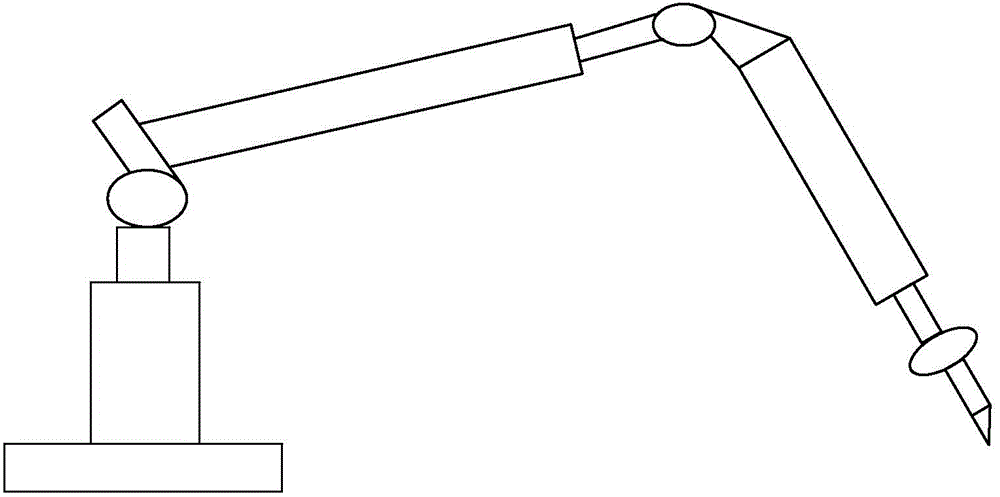
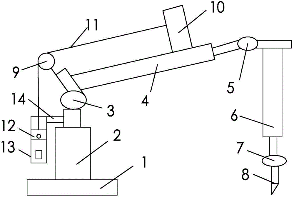
[0014] Such as figure 2 As shown, a measuring mechanism includes a base 1 and a base body 2 above it. The base body 2 is sequentially connected with a joint one 3, a measuring arm one 4, a joint two 5, a measuring arm two 6, a joint three 7 and a measuring arm. Head 8, a pulley 9 is provided above the end connected to the joint one 3 of the measuring arm one 4, and a connecting block 10 is provided above the end connected to the joint two 5; a steel band 11 is also included, and one end of the steel band 11 The connecting block 10 is connected, and the other end is connected with a weight 12 after passing through the pulley 9 .

[0015] The weight 12 is placed in a buffer 13 as a whole, and the buffer 13 is connected to the upper end of the base 2 through a cross bar 14 .

[0016] The present invention bal...


PUM


Abstract

The invention provides a novel measuring mechanism comprising a pedestal and a base arranged above the pedestal. The base is successively connected with a joint 1, a measuring arm 1, a joint 2, a measuring arm 2, a joint 3 and a measuring head. A pulley is arranged above one end, connected to the joint 1, of the measuring arm 1. A connection block is arranged above the other end, connected to the joint 2, of the measuring arm 2. The measuring mechanism further comprises a steel belt which has one end connected to the connection block and the other end connected to a counter weight after passing by the pulley. According to the novel measuring mechanism of the invention, manual operation is easy, the stability of the mechanism is enhanced, and the measuring accuracy is guaranteed.

Description

technical field [0001] The invention relates to a measuring mechanism. Background technique [0002] Testing agencies such as figure 1 As shown, it is often used in the field of mechatronics. It is a mobile and portable manual measurement system. During the actual measurement, the weight of the measurement arm and joints is completely borne by human hands, which will easily make the operator tired and affect the measurement accuracy. Although it can be reduced The components of the mechanical structure and the selection of light materials can reduce the weight of the measuring mechanism, but it cannot be reduced infinitely, that is, this problem cannot be fundamentally solved. In addition, when the measurement is not performed, the two parts of the measuring mechanism The measuring arm, measuring head and joints will naturally sag under the action of their own weight, so that most of the weight of the entire measuring system is biased to one side. In order to prevent the en...

Claims


Application Information

Patent Timeline
IPC IPC(8): G01D11/00
Inventor 布茂振
Owner 布茂振
Why Eureka
Try Eureka