Flow Pattern Discrimination Method and System Based on Spectrum Analysis of Two-phase Flow Pressure Drop Noise

A technology of frequency spectrum analysis and phase flow, which is applied in the field of flow pattern discrimination based on two-phase flow pressure drop noise spectrum analysis and its system field, can solve the problems of no recognition rule given and rough recognition effect, and achieve light weight and structure The effect of simplicity, size and power consumption

Inactive Publication Date: 2018-04-17
SUN YAT SEN UNIV
View PDF5 Cites 0 Cited by
  • Summary
  • Abstract
  • Description
  • Claims
  • Application Information

AI Technical Summary

Problems solved by technology

The recognition of two-phase flow manifolds based on wavelet analysis of DPS noise has been reported, but the author of the paper only pointed out the feasibility, without giving a specific recognition rule, and the recognition effect is relatively rough[5]

Method used


Image

  • Flow Pattern Discrimination Method and System Based on Spectrum Analysis of Two-phase Flow Pressure Drop Noise
  • Flow Pattern Discrimination Method and System Based on Spectrum Analysis of Two-phase Flow Pressure Drop Noise
  • Flow Pattern Discrimination Method and System Based on Spectrum Analysis of Two-phase Flow Pressure Drop Noise

Examples


Embodiment 1

[0076] The flow pattern discrimination method based on the two-phase flow pressure drop noise spectrum analysis of the present invention comprises the following steps:

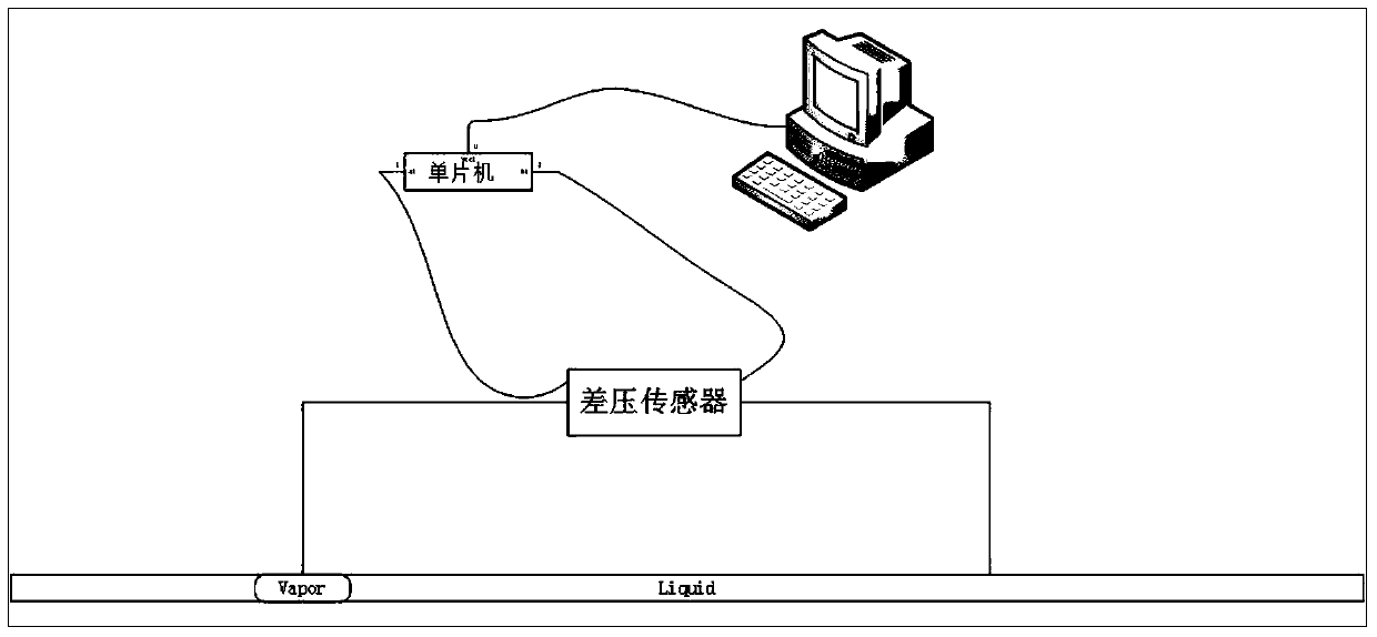
[0077] Step 1: Collect the corresponding continuous pressure drop time-domain signals at both ends of the pipeline measurement section and at both ends of the liquid pump respectively;

[0078] Step 2: performing high-frequency sampling on the continuous voltage drop time-domain signal to obtain a voltage drop time-domain diagram;

[0079] Step 3: transforming the pressure drop time-domain map into a pressure drop spectrogram by using Fast Fourier Transform;

[0080] Step 4: Correlation judgment is made between the pressure drop spectrum diagram at both ends of the pipeline measurement section and the pressure drop spectrum diagram at both ends of the liquid pump, and the category of the two-phase flow is obtained.

[0081] Wherein, if the pressure drop spectrogram corresponding to the pipeline measurement se...

Embodiment 2

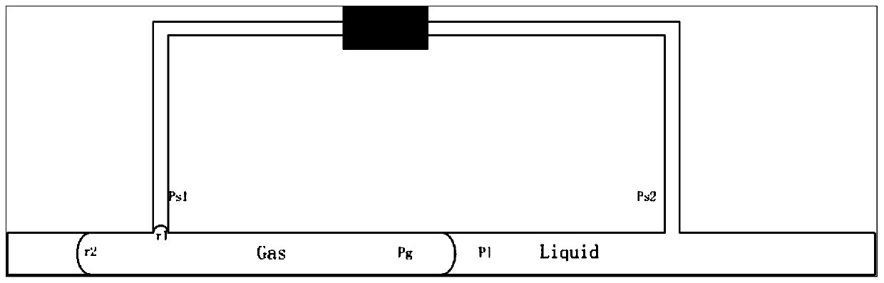
[0126] The water-nitrogen mixed working fluid two-phase pipeline has an inner diameter of 2mm, and the driving force source is air pressure. Schematic see Figure 8 .

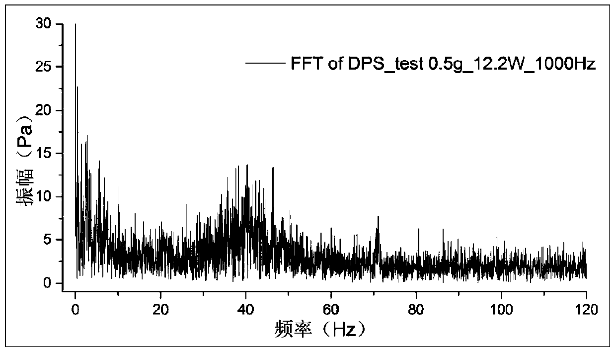
[0127] Select the working condition of slug flow, and make an analog square wave signal diagram related only to the acceleration pressure drop according to the flow process captured by the high-speed camera. Fourier transform, compare the spectrogram of the experimental pressure drop sampling data, the result is as follows Figure 9 shown.

[0128]

[0129] Form Three

[0130] Figure 9 Table 4 shows that the simulated square wave signal spectrum and the experimental pressure drop data spectrum have similar two characteristic noises in the low frequency band, so it can be proved that in the non-pump flooding experimental pipeline, the influence of accelerated pressure drop is also reflected in the pressure drop spectrum In the low-frequency band, the flow pattern can also be preliminarily judged by depr...


PUM


Abstract

The invention discloses a two-phase flow pressure drop and noise spectrum analysis-based flow pattern discrimination method. The method is used for judging the flow pattern of a two-phase flow in a pipeline. The method comprises the steps of respectively acquiring continuous pressure-drop time-domain signals at the two ends of a measurement section of a pipeline and the two ends of a liquid pump; subjecting the continuous pressure-drop time-domain signals to the pressure-drop high-frequency sampling treatment to obtain pressure-drop time-domain figures; judging the relevance between the pressure-drop time-domain figure at the two ends of the measurement section of a pipeline and the pressure-drop time-domain figure at the two ends of the liquid pump to obtain the flow pattern of the two-phase flow. According to the technical scheme of the invention, the two-phase flow pressure drop and noise spectrum analysis-based flow pattern discrimination method has the advantage of accurate recognition effect.

Description

technical field [0001] The invention belongs to the technical field of two-phase flow testing, and in particular relates to a flow pattern discrimination method and system based on two-phase flow pressure drop noise spectrum analysis. Background technique [0002] With the development of aerospace technology, there are more and more scientific experiments under microgravity conditions, and the materials and working fluids used in the experiments are becoming more and more extensive, and it is even possible to carry out production in space in the future. The two-phase flow system has a strong heat dissipation capacity due to the use of latent heat of vapor-liquid phase transition, and has been widely used in the fields of aerospace and civil thermal management. The resistance and heat transfer coefficient of the two-phase flow in the tube depend on the two-phase flow manifold. At present, the discrimination of two-phase manifolds mainly depends on the identification of high-...

Claims


Application Information

Patent Timeline
Patent Type & Authority Patents(China)
IPC IPC(8): G01M10/00
CPCG01M10/00
Inventor 何振辉侯晗威夏佳俊张兴斌
Owner SUN YAT SEN UNIV
Why Eureka
Try Eureka