swivel parking space

A parking space and swivel technology, which is applied in the field of parking spaces, can solve the problems that the front bumper is easy to bump and rub, the environment is not very suitable for the small open space, and the length direction is also greatly affected, so as to achieve a novel and exquisite appearance. The structure is small and safe, and the effect of green area is small

Active Publication Date: 2019-02-12
朱力山
View PDF7 Cites 0 Cited by
  • Summary
  • Abstract
  • Description
  • Claims
  • Application Information

AI Technical Summary

Problems solved by technology

However, the general green areas are separated by steps, and it is difficult for the car to cross the height of the steps. The front bumper of the car is easy to rub against the steeper ramp. In addition, there must be a wider room for the car to turn the road. The space and height that the driver still has to get on and off the car after the car has stopped, and the length direction of the car has a greater impact on the green coverage, so this invention is not very suitable for environments with small open spaces

Method used


Image

  • swivel parking space
  • swivel parking space
  • swivel parking space

Examples


Embodiment 1

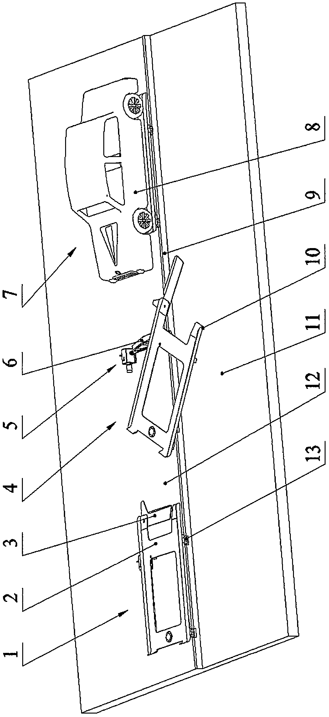
[0023] refer to Figure 1 to Figure 8 . A swivel parking space, comprising a base 16, a vehicle-carrying plate 2, and a power actuator 5, wherein figure 1 It also displays the parking space vacant state 1, the parking space ready to board the car state 4, and the parking space storage state 7.

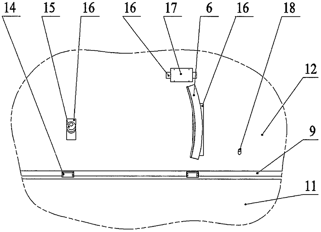
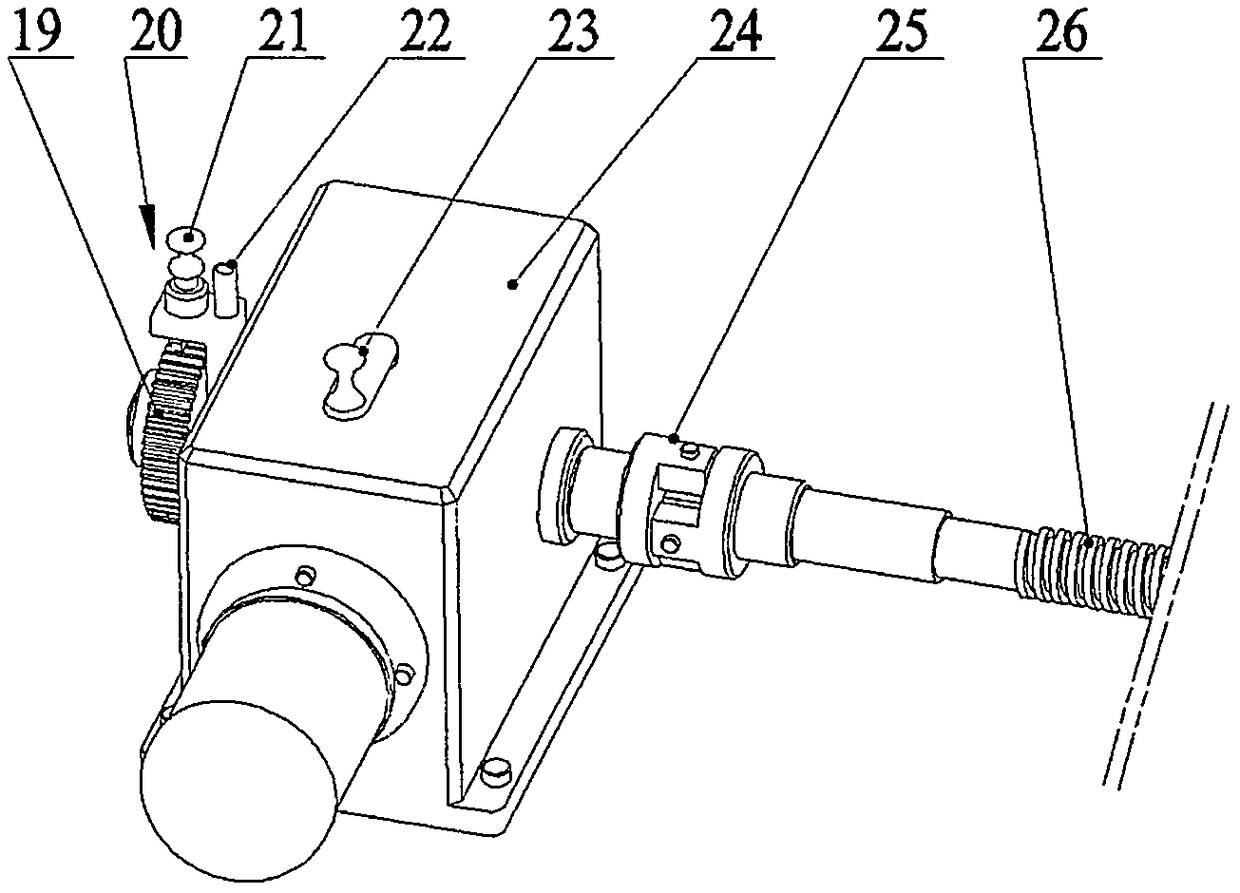
[0024] Described base 16 is fixed on the foundation below lawn 12, and a car plate 2 is contained on the spherical bearing 15 ahead of base 16, and power actuator 5 is contained in the inner side of base 16, and guide rail 6 is contained in In the middle of the base 16, the roller 13 is installed on the edge base 16 of the step 9, the runway extension plate 3 is movably installed on an end of the vehicle-loading plate 2, and the ratchet mechanism 20 is installed on the output end of the motor reducer 24.

[0025] A spherical bearing 15, a power box seat 17, a guide rail 6, two roller seats 14, a driving lever 18 of a runway extension plate 3 are housed on the described base 16; On t...

Embodiment 2

[0037] The main function of the base 16 is to solidify and determine the mutual position and size relationship of each configuration mechanism installed on the base 16, so as to facilitate installation; in this embodiment, each configuration mechanism can also be directly fixed and installed under the ground on a prefabricated basis.

[0038] The structure of the spherical bearing 15 can be replaced by an existing standard self-aligning bearing.

[0039] The transmission mode of the screw rod 26 and the nut assembly 27 in the power actuator 5 can also adopt other hydraulic system oil cylinder mechanisms or power linkage type, gear transmission mode actuators to realize the simple operation of the vehicle board 2. shifting process.

[0040] In addition to the replacement described in the above-mentioned embodiment 2, other structures can follow the relevant structural solutions of the embodiment 1.

[0041] Because the installation environment of the parking space is differen...


PUM


Abstract

The invention relates to a parking space used for parking a car on a roadside, particularly a roadside lawn. Standard parking and convenient and safe operation are realized under a narrow road condition. The invention designs a base fixed below the lawn. A car carrying plate is arranged on a spherical support of the base. As pulleys are arranged on the car carrying plate, the car carrying plate can slide on guide rails of the base. At a step edge opening, the car carrying plate is supported by two rollers, one part of a rotating body of the car carrying plate is moved out of a lawn step by a power actuating mechanism through the action of a screw and nut transmission pair, a car conveniently gets on / off the car carrying plate, and car storage and car fetching are finished. At the same time, the parking space has a structural function of storing and taking a car without power supply. The parking space has the advantages that the parking of a car in a narrow space occasion can be realized on the lawn at night without affecting daytime landscape, and one effective device which cares for people and alleviates community parking pressure is realized.

Description

technical field [0001] The invention relates to a parking space for parking cars on the roadside, especially on the roadside lawn. Background technique [0002] With the development of society, the increase of cars is very fast, causing the shortage of parking spaces in the society. For this reason, many forms of parking garages have occurred. However, it is very difficult to build a new parking garage for the built-up building environment or the difficult situation of parking in the existing community. Therefore, it is common to park on the roadside, and even small cars are parked on the green lawn, which destroys the green environment and management, and some lawn parking spaces have appeared for this reason. But all the lawn parking stalls that have been seen are basically installed on the lawn by the vertical road, and need wider reversing and turning space when parking, which is inconvenient to operate, and has also taken a wider and deeper green area. [0003] In the...

Claims


Application Information

Patent Timeline
Patent Type & Authority Patents(China)
IPC IPC(8): E04H6/06
CPCE04H6/06
Inventor 朱力山
Owner 朱力山
Why Eureka
Try Eureka