Grouting system and grouting method used for composite lining structure backfill and grouting

A grouting system and composite technology, which is applied in the field of underground excavation engineering, can solve the problems of soft grouting conduit material, easy to become smaller grouting channel, and leakage of grouting conduit, so as to improve the grouting effect and solve the problems that cannot be solved. The effect of repeated grouting

Active Publication Date: 2016-06-22
BCEG CIVIL ENG
View PDF7 Cites 12 Cited by
  • Summary
  • Abstract
  • Description
  • Claims
  • Application Information

AI Technical Summary

Problems solved by technology

[0004] The protection and grouting of the backfill grouting system behind the traditional secondary lining structure have the following problems in the field construction: the material of the grouting conduit is soft, and it is easy to deform when it is fixed; during the concrete pouring process, the grouting conduit is squeezed by the concrete, The grouting channel is easy to become smaller or crushed, and the grouting function cannot be realized; the grouting conduit and the grouting equipment are simply connected, and the interface between the conduit and the grouting equipment is easily damaged when the grouting is pressurized; there is leakage in the traditional grouting conduit The risk of grouting pipe exposed on the surface of the secondary lining concrete structure is not good

Method used


Image

  • Grouting system and grouting method used for composite lining structure backfill and grouting
  • Grouting system and grouting method used for composite lining structure backfill and grouting
  • Grouting system and grouting method used for composite lining structure backfill and grouting

Examples


Embodiment Construction

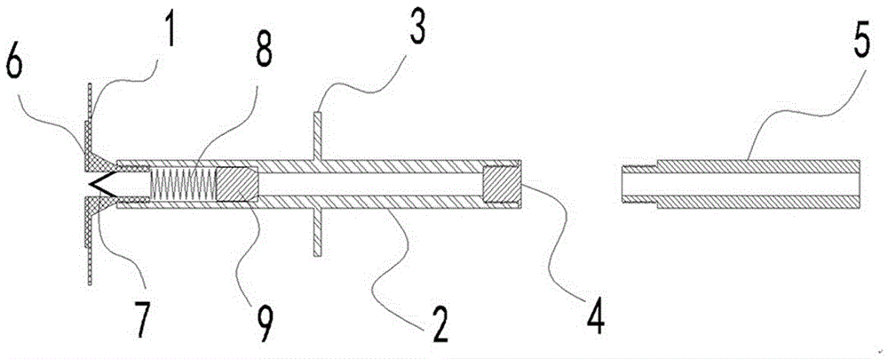
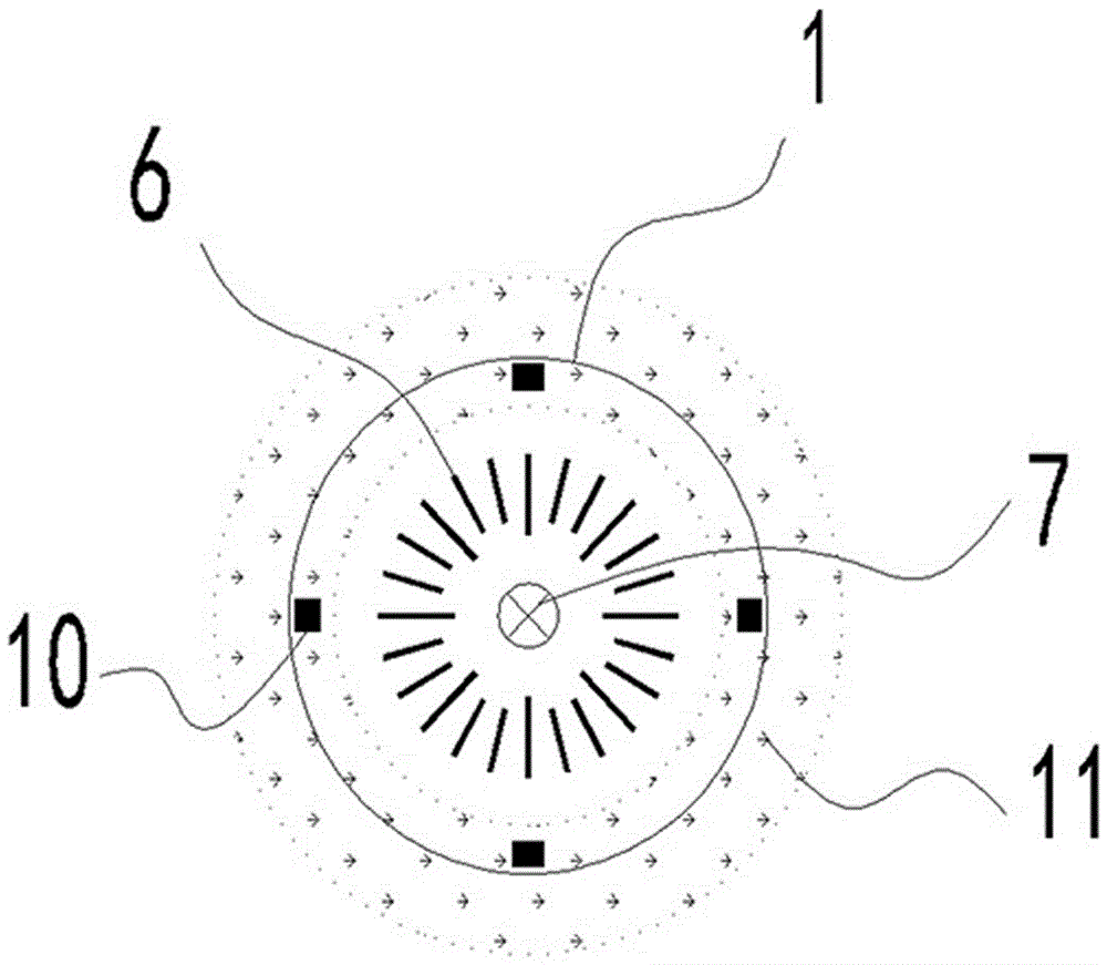
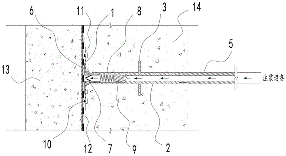
[0046] Hereinafter, embodiments of a grouting system and a grouting method for backfill grouting of a composite lining structure of the present invention will be described with reference to the accompanying drawings.

[0047] The embodiments described herein are specific embodiments of the present invention, are used to illustrate the concept of the present invention, are illustrative and exemplary, and should not be construed as limiting the embodiments of the present invention and the scope of the present invention. In addition to the embodiments described herein, those skilled in the art can also adopt other obvious technical solutions based on the contents disclosed in the claims and the description of the present application, and these technical solutions include any obvious technical solutions to the embodiments described herein. Alternative and modified technical solutions.

[0048] The accompanying drawings in the present specification are schematic diagrams to assist ...


PUM


Abstract

The invention discloses a grouting system and a grouting method used for composite lining structure backfill and grouting.The grouting system comprises a one-way non-return suction cup, a one-way non-return grouting pipe, a water-stopping ring, a sealing plug and a connection pipe, wherein the one-way non-return suction cup is composed of a grouting disc and a non-return hole; the one-way non-return grouting pipe comprises a grouting pipe first end and a grouting pipe second end, a one-way valve is arranged at the grouting pipe first end, and the grouting pipe first end is communicated with a grout inlet of the grouting disc through a screw thread; the water-stopping ring is located on the outer wall of the middle of the one-way non-return grouting pipe; the sealing plug is connected with the grouting pipe second end through a screw thread; the connection pipe comprises a first end and a second end; the first end of the connection pipe is connected with the grouting pipe second end are connected through a screw thread, and the second end of the connection pipe is used for being connected with grouting equipment.The water-stopping ring is additionally arranged on the middle of the grouting pipe, and the water-stopping effect of a contact face between the outer wall of the pipe and a secondary lining structure can be effectively improved.The one-way non-return suction cup is arranged at the tail end of the one-way non-return grouting pipe, repeated grouting can be achieved, and the defect that a traditional grouting system cannot achieve repeated grouting is overcome.

Description

technical field [0001] The invention belongs to the technical field of underground excavation engineering construction, and particularly relates to a grouting system for backfill grouting behind a composite lining structure, and a grouting method realized by using the system. Background technique [0002] Rail transit is the mainstream and development direction of modern urban transportation. It has large capacity, fast speed, low interference and low energy consumption. It is known as the main artery of modern cities. It is a concentrated demonstration of a country's national strength and scientific and technological level, and it is an effective way to alleviate the current situation of traffic congestion in big cities. Shallow burial and underground excavation method is widely used in the construction of underground civil air defense, subway and large underground structures due to its high construction flexibility, good applicability and low site requirements. During the...

Claims


Application Information

Patent Timeline
Patent Type & Authority Applications(China)
IPC IPC(8): E21D11/10E21D11/38
CPCE21D11/105E21D11/38
Inventor 何福军赵萌马晓晖刘雅丹朱义城李全才张立海伍锦鹏辛亮白守兴孔令强王利民
Owner BCEG CIVIL ENG
Why Eureka
Try Eureka