Down light using inner cavity reflector to achieve light distribution and light distribution design method of inner cavity reflector

A technology of reflector and inner cavity, which is applied in the field of light distribution design of the inner cavity reflector of downlights, and can solve problems such as serious glare and uncoordinated ceiling

Inactive Publication Date: 2016-06-22
OPPLE LIGHTING
View PDF5 Cites 0 Cited by
  • Summary
  • Abstract
  • Description
  • Claims
  • Application Information

AI Technical Summary

Problems solved by technology

For example, the batwing light distribution cannot be achieved with the front-mounted mask, and the UGR (Unified Glare Rating) is usually relatively high, resulting in severe glare; and some users do not like to choose the downlight with the built-in mask when decorating because this kind of downlight does not When the lights are turned on, the human eye sees "black holes" one by one, which is inconsistent with the entire horizontal ceiling

Method used


Image

  • Down light using inner cavity reflector to achieve light distribution and light distribution design method of inner cavity reflector
  • Down light using inner cavity reflector to achieve light distribution and light distribution design method of inner cavity reflector
  • Down light using inner cavity reflector to achieve light distribution and light distribution design method of inner cavity reflector

Examples


Embodiment Construction

[0017] The present invention will be fully described below with reference to the accompanying drawings showing embodiments of the invention. However, this invention may be embodied in many different forms and should not be construed as limited to the embodiments set forth herein. Rather, these embodiments are provided so that this disclosure will be thorough and complete, and will fully convey the scope of the invention to those skilled in the art. In the drawings, components are exaggerated for clarity.

[0018] It will be understood that when an "element" is referred to as being "connected" or "coupled" to another element, it can be directly connected or coupled to the other element or intervening elements may be present. In contrast, when an element is referred to as being "directly connected to" or "directly coupled to" another element, there are no intervening elements present. The same reference numerals designate the same elements. As used herein, the term "and / or" i...


PUM


Abstract

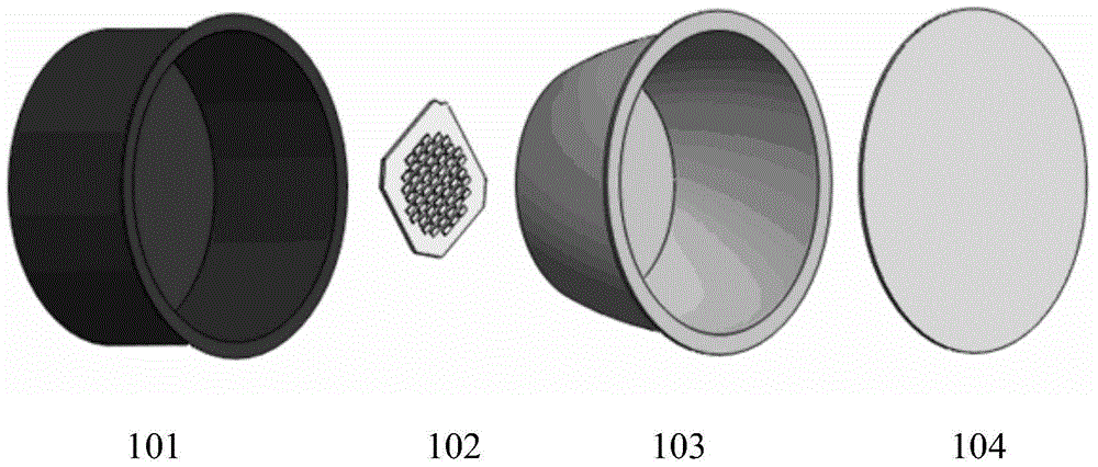
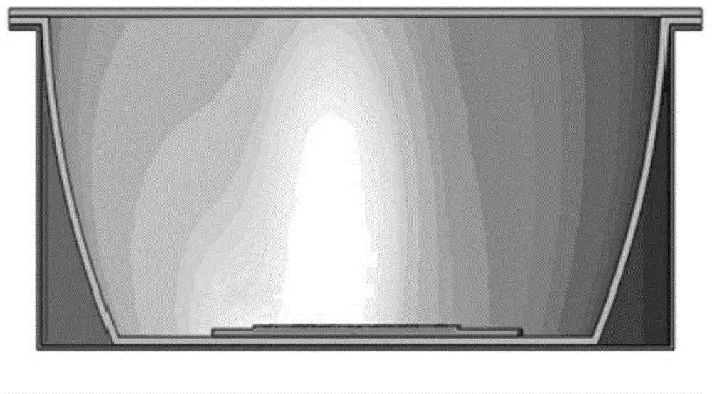
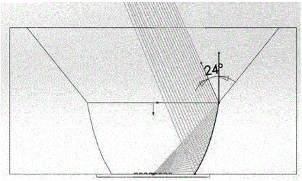
The invention discloses a down light using an inner cavity reflector to achieve light distribution. The down light includes a cavity, a light emitting part, the inner cavity reflector, and a face mask; the light emitting part and the inner cavity reflector are arranged in the cavity; the light emitting part is arranged in a light inlet of the inner cavity reflector; and an arc surface of a side of the inner cavity reflector is designed to be a parabolic surface which can allow light emitted from a geometric centre point of a light source to be parallel to each other via the inner cavity reflector. Through the inner cavity reflector of the down light and different dispersion angles of the light-transmittable face mask, batwing-shaped, water drop-shaped, inverted triangle-shaped, and Lambertian-shaped light distribution can be achieved; different from the conventional down light with a prepositioned dispersion mask, the down light generates an even illuminating effect; and a designer or a user can select the shape of light distribution suitable for themselves as required, and the down light has various functions.

Description

technical field [0001] The invention relates to the field of semiconductor lighting, and more specifically relates to a downlight using an inner cavity reflector for light distribution and a design method for the light distribution of the inner cavity reflector of the downlight. Background technique [0002] LED downlights on the market now generally have two structures, one with a front-facing light-emitting mask and one with a built-in light-emitting mask. [0003] For front-mounted downlights, the light emitted by the LED is usually mixed by the internal diffuse cavity, and then emitted evenly through the diffuser mask to obtain a light distribution similar to Lambertian. [0004] Built-in downlights are usually equipped with external reflectors, which can be diffused or mirrored to achieve batwing or drop-shaped light distribution. [0005] Both of the above have their own unrealizable design flaws. For example, the batwing light distribution cannot be achieved with th...

Claims


Application Information

Patent Timeline
Patent Type & Authority Applications(China)
IPC IPC(8): F21S8/00F21V7/06F21V3/00F21Y101/02
Inventor 刘超博
Owner OPPLE LIGHTING
Why Eureka
Try Eureka