
Oriented X ray combined transillumination method of materials with different thicknesses

An X-ray and combination technology, applied in the field of non-destructive testing, can solve the problems of inability to meet the normal production schedule requirements of products, low dose utilization rate of X-ray field, failure to effectively use available rays, etc. Radiation dose absorption and labor intensity, the effect of solving the problem of detection progress

Active Publication Date: 2016-06-22
CHANGZHI QINGHUA MACHINERY FACTORY +1
View PDF5 Cites 4 Cited by
  • Summary
  • Abstract
  • Description
  • Claims
  • Application Information

AI Technical Summary

Problems solved by technology

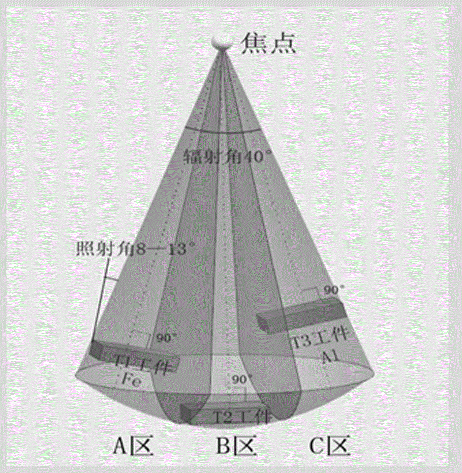
[0002] The X-ray beam generated by the directional X-ray machine is radiated at a cone angle of 40°. During the inspection, the workpiece (or weld) is required to be arranged perpendicular to the central beam. The layout plane and the beam space form an X-ray conical transillumination field. The irradiation angle (crack The detection angle) is required to be no more than 13°, so that the actual use of rays is very small, and the available rays cannot be effectively used, which results in piece-by-piece (piece-by-piece) flow operations during the transillumination process, which largely limits the detection progress for batch workpieces
[0003] According to the analysis of the actual X-ray detection situation, the use of directional X-ray conical transillumination field for vertical transillumination of the workpiece has the following disadvantages: the dose utilization rate of the X-ray field is low, generally only 22%, resulting in energy waste; X-ray detection efficiency Low, unable to meet the normal production schedule requirements of the product; no combined transillumination for materials of different thicknesses
[0004] According to this existing technology, it is difficult to efficiently complete the X-ray detection operation of different thickness material combinations

Method used


Image

  • Oriented X ray combined transillumination method of materials with different thicknesses
  • Oriented X ray combined transillumination method of materials with different thicknesses
  • Oriented X ray combined transillumination method of materials with different thicknesses

Examples


Embodiment Construction

[0039] The present invention will be further described below in conjunction with specific examples.

[0040] A method for combined directional X-ray transillumination of materials with different thicknesses, specifically comprising the following steps:

[0041] a. Select the combined product workpiece, and select the welded and polished 6, 8, 10mm welding test plates with similar shape, size and structure for combination;

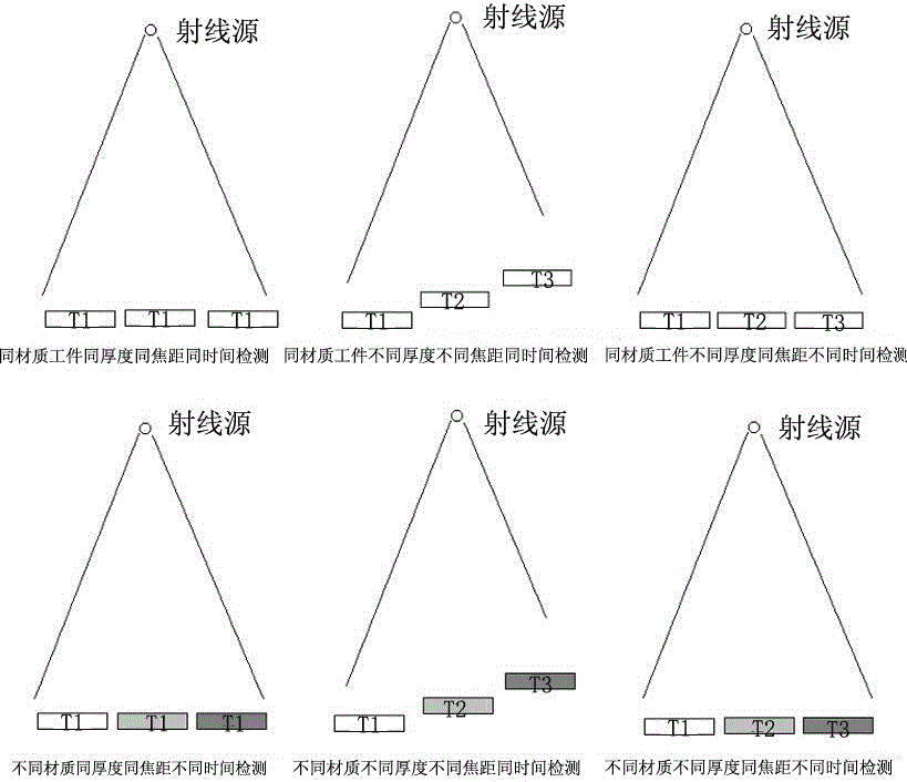
[0042] b. Determine the combination method, and the following combinations can be carried out for the selected workpiece: same focal length and same time detection, different focal length and different time detection, same focal length and different time detection;

[0043] c. Determine the transillumination parameters, the specific transillumination parameters are shown in Table 5 below.

[0044] Table 5 Transillumination parameters

[0045]

[0046] d. Carry out transillumination, after selecting the transillumination parameters, conduct directional ...


PUM


Abstract

The invention relates to an oriented X ray combined transillumination method of materials with different thicknesses and particularly relates to the technical field of nondestructive testing in industries including aviation, aerospace, weapons, ships, special equipment and the like. Aiming at solving the technical problems, the oriented X ray combined transillumination method of the materials with the different thicknesses, which can realize combined transillumination of the same materials or different materials with different thicknesses, and can improve the detection efficiency, is provided. The adopted technical scheme comprises the following steps: selecting a combined product workpiece; determining a combination manner; determining transillumination parameters and carrying out transillumination and dark room treatment; selecting product workpieces with the same or similar shapes, sizes and structures and combining; or selecting product workpieces with different shapes, sizes and structures and combining, wherein the oriented X ray combined transillumination manner of the materials with the different thicknesses can be realized by a plurality of different combination manners.

Description

technical field [0001] The invention relates to a directional X-ray combined transillumination method for materials with different thicknesses, in particular to the technical field of non-destructive testing in industries such as aviation, aerospace, weapons, ships and special equipment. Background technique [0002] The X-ray beam generated by the directional X-ray machine is radiated at a cone angle of 40°. During the inspection, the workpiece (or weld) is required to be arranged perpendicular to the central beam. The layout plane and the beam space form an X-ray conical transillumination field. The irradiation angle (crack The detection angle) is required to be no more than 13°, so that the actual use of rays is very small, and the available rays cannot be effectively used, which results in piece-by-piece (piece-by-piece) flow operations during the transillumination process, which largely limits the detection progress for batch workpieces. [0003] According to the analys...

Claims


Application Information

Patent Timeline
Patent Type & Authority Applications(China)
IPC IPC(8): G01N23/02
Inventor 韩壮壮刘小明赵振武程建成沈云霄柳育红董辉李海燕王云飞赵丽霞郭智
Owner CHANGZHI QINGHUA MACHINERY FACTORY
Learn More