
A constant current and constant voltage control method and circuit for primary side feedback

A technology of constant current and constant voltage control and primary side feedback, which is applied in the direction of control/regulation system, regulation of electrical variables, instruments, etc., can solve the problems of high cost and complex circuit, so as to save costs, avoid timing competition problems, avoid The effect of the risk of parasitic effects

Active Publication Date: 2017-05-24
CRM ICBG (WUXI) CO LTD
View PDF6 Cites 0 Cited by
  • Summary
  • Abstract
  • Description
  • Claims
  • Application Information

AI Technical Summary

Problems solved by technology

[0026] In view of the shortcomings of the prior art described above, the purpose of the present invention is to provide a constant current and constant voltage control method and circuit for primary side feedback, which is used to solve the problem of constant current and constant voltage control in the existing primary side feedback control technology. Implemented in two independent ways, there are timing competition risks and parasitic effects, resulting in complex circuits and high costs.

Method used


Image

  • A constant current and constant voltage control method and circuit for primary side feedback
  • A constant current and constant voltage control method and circuit for primary side feedback
  • A constant current and constant voltage control method and circuit for primary side feedback

Examples


Embodiment Construction

[0061] The following describes the implementation of the present invention through specific specific examples, and those skilled in the art can easily understand other advantages and effects of the present invention from the content disclosed in this specification. The present invention can also be implemented or applied through other different specific embodiments, and various details in this specification can also be modified or changed based on different viewpoints and applications without departing from the spirit of the present invention.

[0062] Please refer to the attached picture. It should be noted that the illustrations provided in this embodiment only illustrate the basic idea of ​​the present invention in a schematic way, and the figures only show the components related to the present invention instead of the number, shape, and shape of the components in actual implementation. For size drawing, the type, quantity, and proportion of each component can be changed at wi...


PUM


Abstract

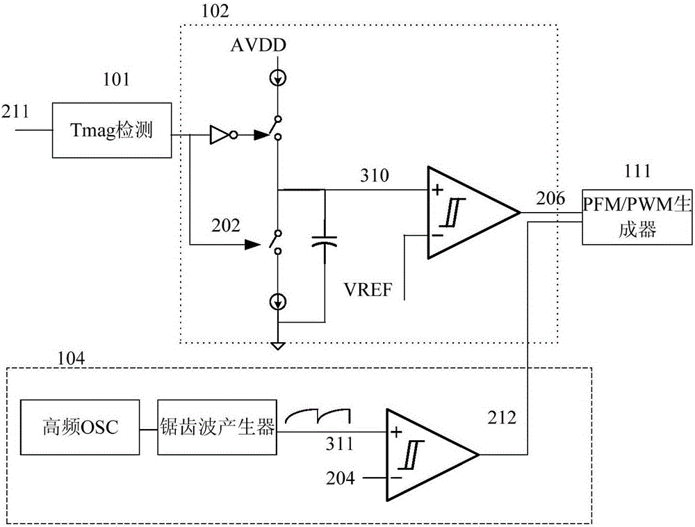
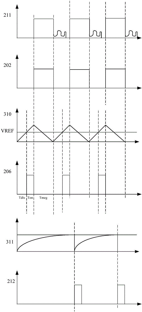
The invention provides a constant current and constant voltage control method and circuit for primary side feedback. The circuit comprises a demagnetizing time converter which is used for detecting demagnetizing time and converting the demagnetizing time into demagnetizing time voltage signals; a frequency adjuster used for generating constant voltage clock frequency control signals; an oscillator which generates sawtooth signals under the control of the constant voltage clock frequency control signals, and generates constant current clock start signals by comparing the values of the sawtooth signals and the values of the demagnetizing time voltage signals or generates constant voltage clock start signals by comparing the values of the sawtooth signals and the values of preset constant voltage and constant current dividing voltage. A novel method is used for generating the CC / CV start clock signals and one start clock generator can be shared, so that the problem of time sequence competition possibly caused by two paths of signals is effectively solved; an oblique wave generating circuit is removed so that the cost is reduced; the generation of high frequency signals is not needed, so that the risk of a parasitic effect is prevented.

Description

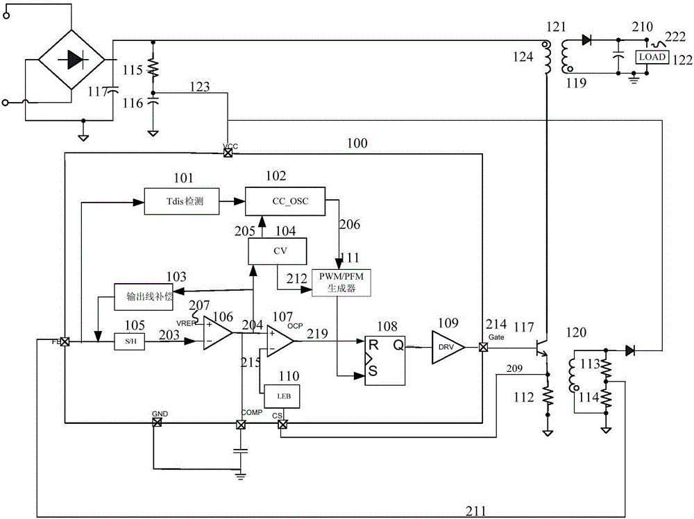
Technical field [0001] The invention belongs to the technical field of electronic circuits, and relates to a constant current and constant voltage control method and system, in particular to a constant current and constant voltage control method and circuit for primary side feedback. Background technique [0002] In the existing circuit implementation of the primary-side feedback control chip, since the constant current or constant voltage control method is relatively complicated, the constant current circuit and the constant voltage circuit are usually processed by two different circuits. [0003] See figure 1 As shown, the primary-side feedback constant current and constant voltage controller 100 includes: a demagnetization time (Tdis) detector 101 for detecting the demagnetization time and generating a signal for determining CC / CV (constant current / constant voltage); an oscillator 102 , Used to generate a clock start signal; line compensation generator 103, used to generate line...

Claims


Application Information

Patent Timeline
Patent Type & Authority Patents(China)
IPC IPC(8): G05F1/56
Inventor 林昌全李进俞秀峰胡津华盛欢
Owner CRM ICBG (WUXI) CO LTD
Learn More