Battery management system with low standby power consumption and battery management system awaking method
A battery management system and low power consumption technology, which is applied in secondary battery testing, secondary battery repair/maintenance, etc., can solve the problems of shortening battery standby time, high standby power consumption of the management system, etc., to reduce standby power consumption, Low cost and extended standby time
- Summary
- Abstract
- Description
- Claims
- Application Information
AI Technical Summary
Problems solved by technology
Method used
Image

Examples
Embodiment 1
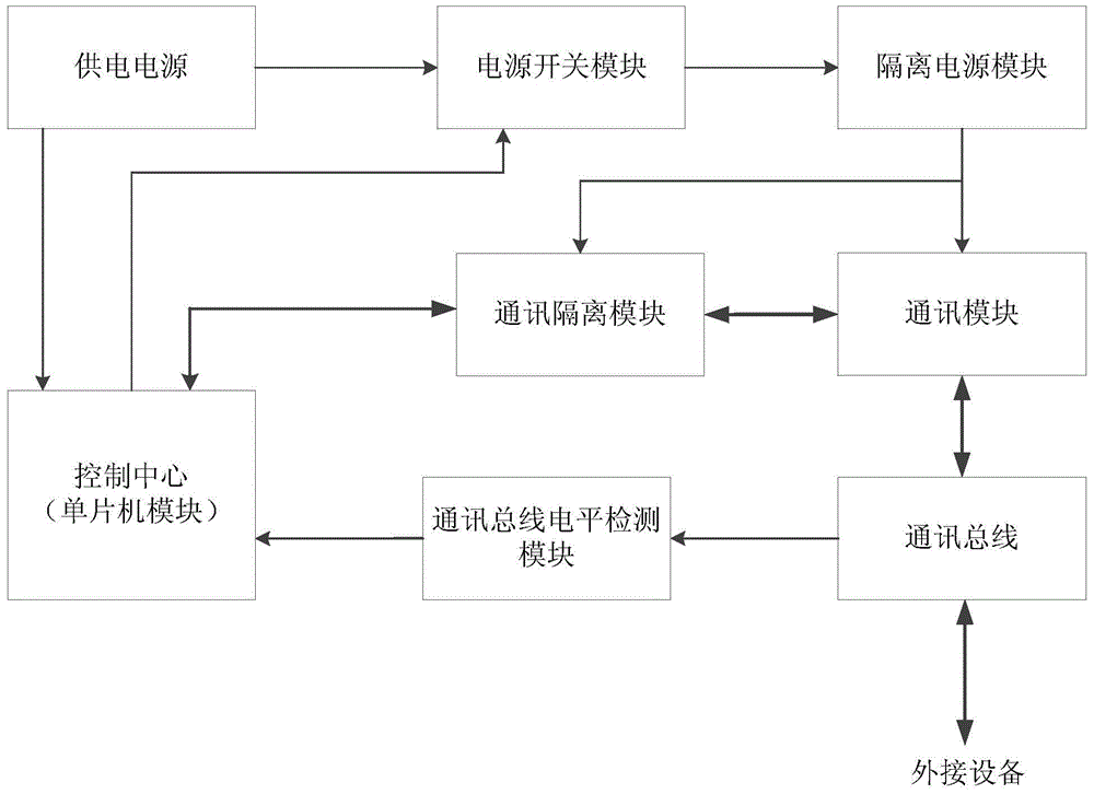
[0031] Embodiment 1 of the present invention provides a low power consumption standby battery management system. refer to figure 1 , the low-power standby battery management system includes: a power supply, an isolated power supply module, a communication module, a communication bus, a communication isolation module, a control center, a power switch module, and a communication bus level detection module. The output end of the power supply is connected to the input end of the power switch module, the output end of the power switch module is connected to the input end of the power isolation module, and the output end of the power isolation module is respectively connected to the power supply input end of the communication module and the communication isolation module. The power supply input terminal is connected, the communication module is respectively connected with the communication bus and the communication isolation module signal, the communication isolation module is conne...
Embodiment 2
[0036] Embodiment 2 of the present invention provides a low power consumption standby battery management system. refer to Figure 4 , the difference between the present embodiment and embodiment 1 is as follows:
[0037] The controllable switch device uses a PNP transistor Q2. The power switch module also includes a resistor R2 connected between the base and the emitter of the PNP transistor, the base of the PNP transistor Q2 is connected to the output end of the power supply as the input of the power switch module, and the emitter of the PNP transistor Q2 The pole serves as the input control terminal of the power switch module and is connected to the output control terminal of the control center, and the collector of the PNP transistor Q2 is connected to the input terminal of the power isolation module as the output terminal of the power switch module.
Embodiment 3
[0039] Embodiment 3 of the present invention provides a battery management system wake-up method based on the low-power standby battery management system described in Embodiment 1. refer to Figure 5 and combine figure 1 , figure 2 , image 3 , the wake-up method of the battery management system includes the following steps:
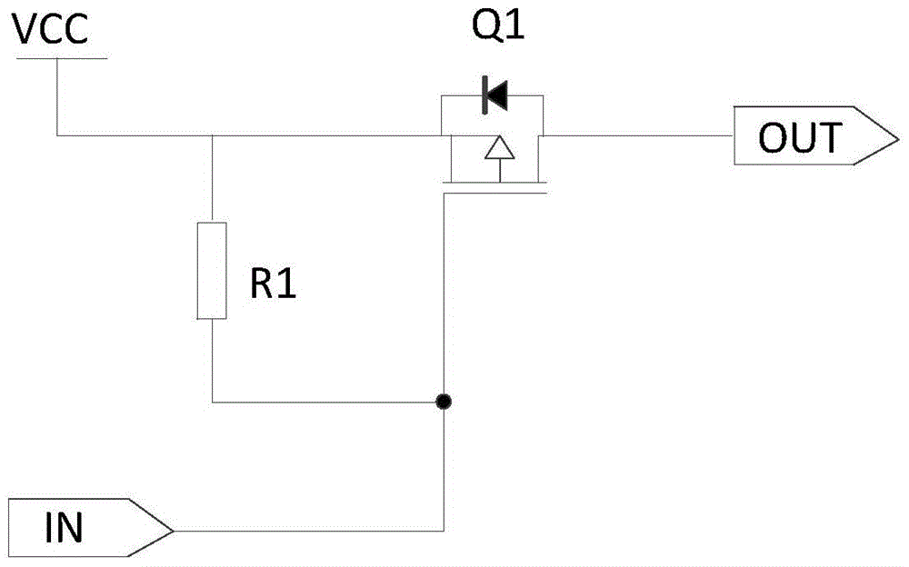
[0040] (1) When the battery management system is in standby, the control center disconnects the power switch module. Specifically: when the battery management system is in standby, the control center outputs a high-level control signal to the gate of the P-type MOS transistor Q1 through the output control terminal, the P-type MOS transistor Q1 is cut off, and the power switch module has no power output, so the Power off the isolated power supply module, communication module, and communication isolation module.
[0041] (2) The communication bus level detection module detects the level signal of the communication bus.
[0042] (3) If it is detected...
PUM
 Abstract
Description
Claims
Application Information
 - Generate Ideas
- Intellectual Property
- Life Sciences
- Materials
- Tech Scout
- Unparalleled Data Quality
- Higher Quality Content
- 60% Fewer Hallucinations
Browse by: Latest US Patents, China's latest patents, Technical Efficacy Thesaurus, Application Domain, Technology Topic, Popular Technical Reports.
© 2025 PatSnap. All rights reserved.Legal|Privacy policy|Modern Slavery Act Transparency Statement|Sitemap|About US| Contact US: help@patsnap.com