
Adjusting device for linear array camera scanning imaging

A line scan camera and adjustment equipment technology, applied in optics, instruments, photography, etc., can solve the problems of difficult alignment and low efficiency, and achieve the effects of simple alignment steps, high alignment accuracy, and fast alignment speed

Active Publication Date: 2016-06-29
BEIJING LONGERICH TECH CO LTD
View PDF5 Cites 2 Cited by
  • Summary
  • Abstract
  • Description
  • Claims
  • Application Information

AI Technical Summary

Problems solved by technology

In the prior art, in order to achieve the alignment of the shooting line of the line camera and the light of the line light source, the line camera or the line light source are completely manually rotated to align the shooting line and the light, and the alignment is difficult and low efficiency

Method used


Image

  • Adjusting device for linear array camera scanning imaging
  • Adjusting device for linear array camera scanning imaging
  • Adjusting device for linear array camera scanning imaging

Examples


Embodiment Construction

[0030] The following will describe specific implementations of the linear camera device according to the present invention with reference to the accompanying drawings. The following detailed description and drawings are used to illustrate the principles of the present invention. The present invention is not limited to the described preferred embodiments, and the protection scope of the present invention is defined by the claims.

[0031] Furthermore, spatially relative terms such as "upper," "lower," "left," and "right," etc., are used to describe the relative positional relationship of one element to another as shown in the drawings. Accordingly, spatially relative terms may be applied in directions other than those shown in the figures when used. Obviously, while all these spatially relative terms refer to the directions shown in the figures for ease of illustration, those skilled in the art will understand that directions other than the directions shown in the figures may b...


PUM


Abstract

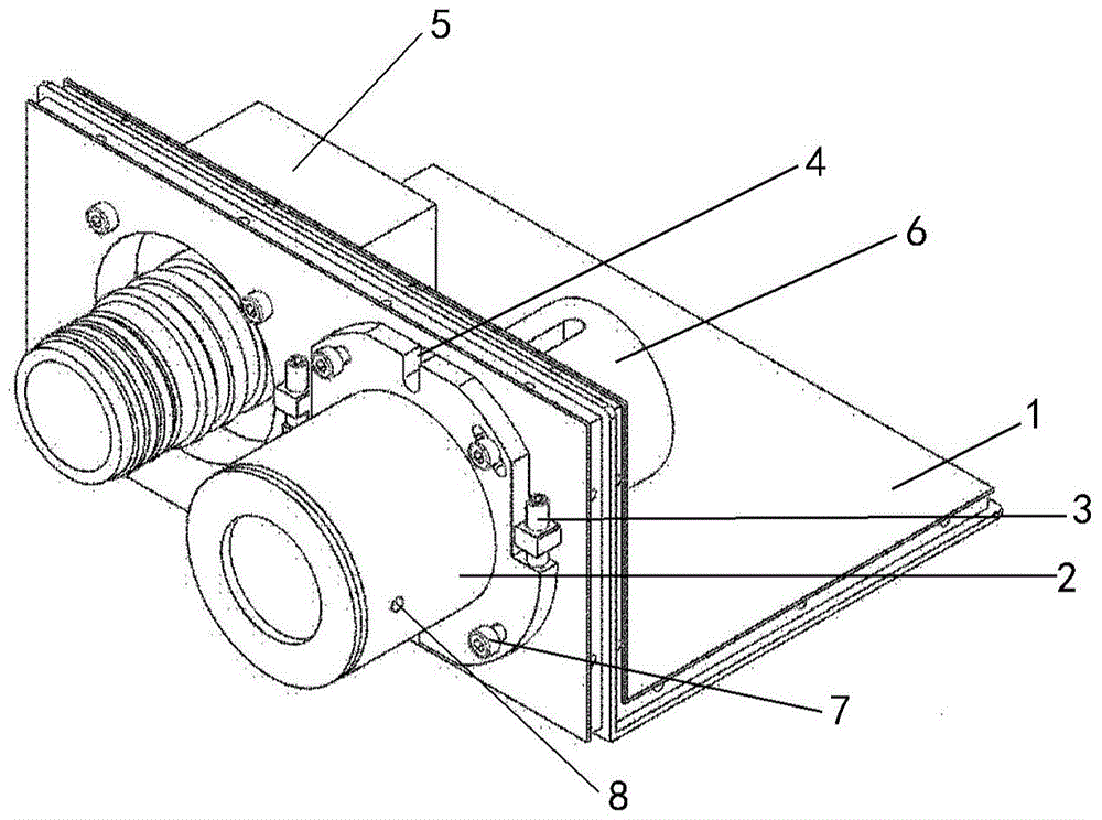
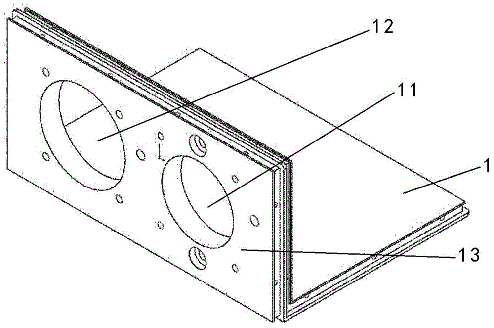
The invention relates to an adjusting device for linear array camera scanning imaging. The adjusting device comprises an installation plate, a connecting piece, a first adjusting module and a second adjusting module. The installation plate is used for installing one of a linear array camera and a linear light source, the connecting piece is used for installing the other of the linear array camera and the linear light source, and the connecting piece is installed on the installation plate. The first adjusting module is used for adjusting the pitch angle of the connecting piece. The second adjusting module is used for enabling the connecting piece to rotate. A linear shooting device achieves alignment of shooting lines of the linear array camera and light rays of the linear light source through the adjusting device, the alignment steps are simple, the alignment speed is high, and the alignment precision is high.

Description

technical field [0001] The invention relates to the technical field of detection equipment, in particular to an adjustment equipment for scanning imaging of a line array camera. Background technique [0002] During the operation of the subway network, if there are hidden dangers in the tunnel structure and surrounding rock and soil, the tunnel will be subjected to the load and vibration of the subway train, and the tunnel structure will be deformed and cracked, which will affect the safety of the subway operation. [0003] Therefore, in the process of subway tunnel acceptance and operation, the detection of tunnel surface cracks is very important. Manual measurement is a commonly used method in tunnel inspection technology at present. Manual measurement has low efficiency, poor reliability, and is easy to miss inspection. The judgment of crack level mainly depends on experience. Moreover, for the subway network of hundreds of kilometers to several thousand kilometers, it is...

Claims


Application Information

Patent Timeline
IPC IPC(8): G01N21/88G03B15/03
CPCG03B15/03G01N21/88
Inventor 刘永强任云涛
Owner BEIJING LONGERICH TECH CO LTD
Learn More