Linear light spot module

A line spot and module technology, applied in optics, instrumentation, photography, etc., can solve the problems of poor positioning accuracy, difficult adjustment of deviation angle, and affecting work efficiency, etc., achieving fast alignment, simple alignment steps, and accurate alignment high precision effect

Inactive Publication Date: 2017-07-07
WUXI LUMISOURCE TECH
View PDF10 Cites 3 Cited by
  • Summary
  • Abstract
  • Description
  • Claims
  • Application Information

AI Technical Summary

Problems solved by technology

[0003] During use, the camera’s strip-shaped field of view needs to be consistent with the linear light spot of the laser light source. When the strip-shaped field of view is inconsistent or deviated from the linear spot, it will cause the incomplete part of the captured picture to have no image, resulting in the inability to obtain a clear picture of the truck parts. The system cannot effectively identify the faults of the captured pictures, which seriously affects the work efficiency and leaves hidden dangers for the safety of trucks.
[0004] In the prior art, in order to realize the alignment of the strip-shaped field of view and the linear spot of the line-scan camera, the line-scan camera or the laser light source is directly rotated by hand to align the strip-shaped field of view and the linear spot, which is difficult and inefficient. , the positioning accuracy is poor, and the deviation angle is not easy to adjust

Method used


Image

  • Linear light spot module
  • Linear light spot module
  • Linear light spot module

Examples


Embodiment 1

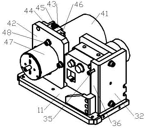
[0026] Such as Figure 1 to Figure 6 As shown, the line spot module includes a camera 21 and a laser light source 41, the camera 21 and the laser light source 41 are respectively located at the two ends of the base 11, the camera 21 is installed on the camera angle adjustment device, and the camera angle adjustment device is installed On the base 11 , the laser light source 41 is installed on a light source angle adjustment device, and the light source angle adjustment device is installed on the base 11 .

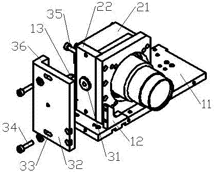
[0027] The camera angle adjustment device includes a side fixing plate 32 and an angle adjustment plate 36 all fixed on the base 11, a rotating shaft 31, a spring A37 and a limiting plate 35; the limiting plate 35 is fixed on the camera 21 away from the laser light source. On one side of 41, the limiting plate 35 is provided with shaft holes and threaded holes; the side fixing plate 32 is located on one side of the limiting plate 35, and the side fixing plate 32 is provided...

Embodiment 2

[0033] On the basis of the above examples, if Figure 1 to Figure 5 As shown, the angle adjusting plate 36 is fixed on the base 11 through the rear fixing plate 13, the side fixing plate 32 is fixed on the base 11 through the front fixing plate 12, and the angle adjusting plate 36 and the side fixing plate 32 are integral structure, forming an L shape.

[0034] The side fixing plate 32 and the angle adjusting plate 36 are made into an integral structure with good strength and easy assembly.

[0035] Front fixed plate 12 and rear fixed plate 13 improve stability.

Embodiment 3

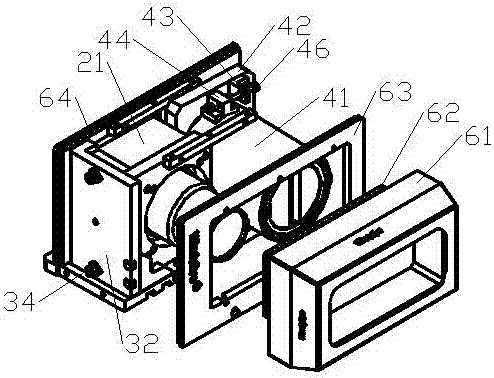
[0037] On the basis of the above examples, if figure 1 and Figure 7 As shown, it also includes a window cover 61, a panel 63, a cover 65 and a rear cover 64, the panel 63 and the rear cover 64 are respectively fixed on both sides of the base 11, and the cover 65 is fixed on the panel 63 and the rear Between the cover plates 64, the window cover 61 is fixed on the panel 63, the camera 21 and the laser light source 41 are located inside the window cover 61, and the window cover 61 is equipped with a light-transmitting protective sheet.


PUM


Abstract

The invention relates to a lens module of optical detection equipment, particularly to a linear light spot module. The linear light spot module comprises a camera and a laser light source; the camera and the laser light source are positioned at the two ends of a base respectively; the camera is mounted on a camera angle adjustment apparatus; the camera angle adjustment apparatus is mounted on the base; the laser light source is mounted on a light source adjustment apparatus; and the light source adjustment apparatus is mounted on the base. The linear light spot module provided by the invention has the advantages of simple steps of realizing band-shaped view of the linear array camera and alignment of the linear light spot of the laser light source, and high alignment speed, high alignment precision and the like.

Description

technical field [0001] The invention relates to a lens module of optical detection equipment, in particular to a line spot module. Background technique [0002] In order to ensure the safety of railway wagons, the railway system has promoted the application of (trucks, passenger cars, EMUs) trackside fault dynamic image detection system. In this system, a high-speed industrial digital black and white camera is used to take pictures of the parts of the wagons that need to be detected. , and then the detection system detects the pictures of the car body parts taken, and automatically judges whether there is a fault. [0003] During use, the camera’s strip-shaped field of view needs to be consistent with the linear light spot of the laser light source. When the strip-shaped field of view is inconsistent or deviated from the linear spot, it will cause the incomplete part of the captured picture to have no image, resulting in the inability to obtain a clear picture of the truck p...

Claims


Application Information

Patent Timeline
Patent Type & Authority Applications(China)
IPC IPC(8): G03B15/03G03B15/05
CPCG03B15/03
Inventor 芮建保王永春韦春雷李大明
Owner WUXI LUMISOURCE TECH
Why Eureka
Try Eureka