A new type of gyromagnetic device
A new type of magnetic equipment and technology, applied in the field of new gyromagnetic equipment, can solve the problems of unstable structure of gyromagnetic equipment, insufficient optimization of magnetic field distribution, poor magnetic health care effect, etc., and achieve high effective utilization of magnetic field and better magnetic health care effect Good, beneficial to the effect of strong magnetic field
- Summary
- Abstract
- Description
- Claims
- Application Information
AI Technical Summary
Problems solved by technology
Method used
Image
Examples
Embodiment 1
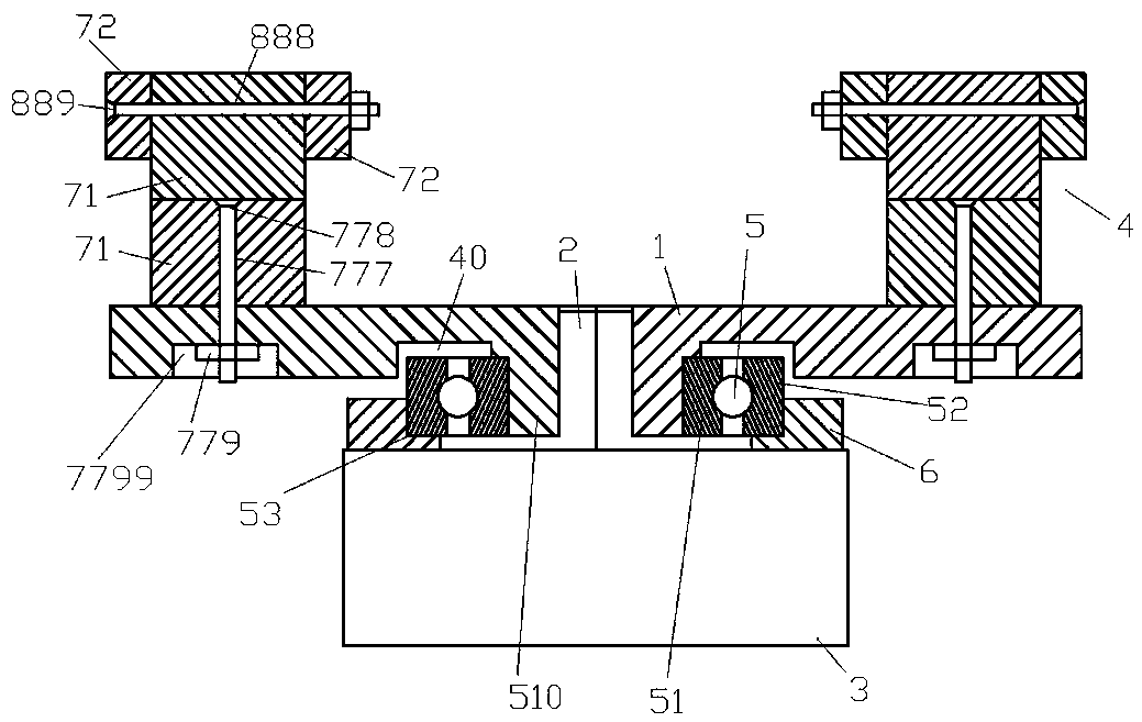
[0029] Example 1, such as figure 1 , 2 As shown, a new type of gyromagnetic device includes a rotating plate 1, the rotating plate 1 is connected to a rotating drive shaft 2, the rotating drive shaft 2 is connected to a motor 3, and the rotating plate 1 is provided with a magnetic field source 4, An assembly bearing device is also arranged under the rotating plate 1. Assembling the carrying device can not only complete the effective coordination with the rotating plate 1, but also carry the larger weight of the upper part, reduce the motor load, reduce the wear of the motor bearing, reduce the required power, extend the life of the motor and reduce the temperature rise of the motor, During operation, the stability of the entire structure is ensured, and the setting of the assembly bearing device should not affect the normal rotation of the rotating plate 1, but should ensure that the rotating plate 1 rotates more effectively and smoothly.
[0030] The assembling and carrying devi...
Embodiment 2
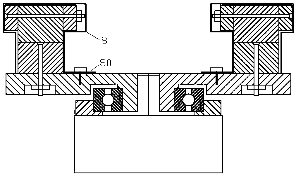
[0037] Example 2, such as image 3 As shown, the difference from Embodiment 1 is that a protective cover 8 is provided on the outside of the magnetic field source 4, and the protective cover 8 is a non-magnetic stainless steel cover. The lower part of the protective cover 8 can be extended to form a fixed connection with the rotating plate 1. The cover mounting piece 80 can be installed and fixed to the rotating plate 1 by screws, etc. The protective cover 8 is a non-magnetic stainless steel cover, that is, a non-magnetic stainless steel cover can be used, which is beautiful and protects the magnetic pole pieces from being Oxidation and avoiding the direct collision and contact of ferromagnetic objects with the magnetic pole block can also prevent the magnetic field source 2 from falling off during high-speed operation and causing accidents, further optimizing the structure and force distribution, improving various physical properties, and improving the magnetic health effect. T...
Embodiment 3
[0038] Example 3, such as Figure 4 , 5 As shown, the difference from Embodiment 1 lies in the design of the magnetic field source 4. In this embodiment, the main magnetic pole piece 71 can be arranged in a cylindrical structure, and the auxiliary magnetic pole piece 72 is arranged at a position above the main magnetic pole piece 71. It is in contact with the side of the main magnetic pole piece 71 and has a sufficient distance with the rotating plate 1 without contact. A plurality of auxiliary magnetic pole pieces 72 can be arranged and can be assembled into a square structure or a ring structure to surround the main magnetic pole piece 71. An eccentric enclosure structure or a central enclosure structure is formed, or a single auxiliary magnetic pole piece 72 in the shape of a mouth or a ring is used to surround the main magnetic pole piece 71. The magnetic poles of the main magnetic pole piece 71 are arranged along the longitudinal direction and are opposite to each other. Th...
PUM
 Abstract
Description
Claims
Application Information
 - R&D
- Intellectual Property
- Life Sciences
- Materials
- Tech Scout
- Unparalleled Data Quality
- Higher Quality Content
- 60% Fewer Hallucinations
Browse by: Latest US Patents, China's latest patents, Technical Efficacy Thesaurus, Application Domain, Technology Topic, Popular Technical Reports.
© 2025 PatSnap. All rights reserved.Legal|Privacy policy|Modern Slavery Act Transparency Statement|Sitemap|About US| Contact US: help@patsnap.com


